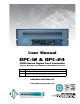
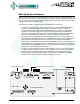
User Manual DPC-12 & DPC-24 3000 Series Digital Pack Controller Control Retrofit for CD80 Portable Dimmer Packs Model DPC-12 DPC-24 Description CD80 12 x 2.4kW, 6 x 6kW and 6 x 12kW Portable Dimmer Packs. CD80 24 x 1.2 kW and 24 x 2.4kW Portable Dimmer Packs CD80 48 x 2.4kW Compact Rolling Racks (requires 2 per rack). JOHNSON SYSTEMS INC. www.johnsonsystems.
Table of Contents Warranty...........................................................................................................2 Introduction.......................................................................................................3 Packaging & Contents......................................................................................3 Installation........................................................................................................3 DPC-24/12 Circuit Board...........
Introduction DPC-12 Digital Pack Controllers (DPC’s) are a next generation retrofit electronics package designed specifically for upgrading Strand CD80 12 channel and 24 channel portable dimmer packs, as well as 48 channel compact rolling racks. This direct plug-in replacement control module supersedes all previous generations of OEM and aftermarket controllers in both reliability and features. “Basic Mode”, on power up, was designed specifically at the request of major U.S. studios and rental houses.
DA EEPROM BACKUP & FIRMWARE UPDATE PIN 13 15 16 FUNCTION DMX-B Input Data+ DMX-B Input DataDMX-B Input Shield / Common FAN FUSE REPLACE WITH 3000 SERIES on a terminal block mounted 2A 250V If the DMX input is connected internally, FAST-ACTING GMA TYPE CD80 DIGITAL PACKpack, CONTROLLER inside the CD80 dimmer jumpers will need to be moved on the FUSE ONLY! REV.1 1132 DPC-24/12 circuit board to enable the DMX-B input.
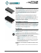
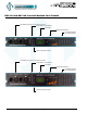
DPC-24/12 Circuit Board The DPC-24/12 circuit board is the central electronic control system (a.k.a. brain) for DPC-12 and DPC-24 retrofit control modules. The edge connectors (EDGE1, EDGE2, EDGE3 and EDGE5 (for DPC-24 only)) located on the upper edge of the DPC-24/12 circuit board connects with the OEM connectors inside the CD80 dimmer pack.
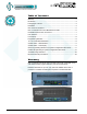
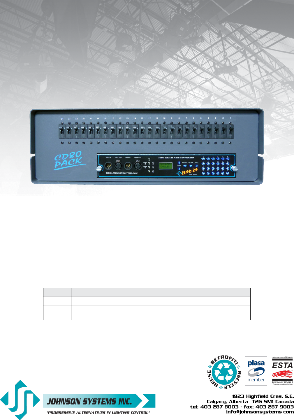
DPC-12 and DPC-24 Control Module Face Panels Dual DMX Input and Thru Connectors (5-Pin XLR) System Status - LED Indicators LCD Display Programming Switches Local Button/Switches (a.k.a. Bump Buttons) Infrared (I/R) LED for Printer Dual DMX Input and Thru Connectors (5-Pin XLR) System Status - LED Indicators LCD Display Programming Switches Local Button/Switches (a.k.a. Bump Buttons) Infrared (I/R) LED for Printer 6 www.johnsonsystems.
DMX Input and Thru 5-Pin XLR Connectors PIN 1 2 3 4 5 FUNCTION DMX Shield / Common DMX DataDMX Data+ Pass Thru Connection Pass Thru Connection Dual DMX Input and Thru Connectors DPC-12 and DPC-24 control modules are equipped with dual (2) optoisolated DMX inputs. The DMX-A and DMX-B input and thru connectors (5pin XLR) are located on the front panel of the control module. A built-in DMX protocol manager can be configured for various applications.
LCD Display The LCD display is capable of displaying 2 lines of 8 characters. A backlight automatically comes on when activity is sensed. The LCD contrast can be easily adjusted for optimum viewing. Refer to menu item “LCD VIEW” on page 22 for further details. Programming Switches The MENU UP/DOWN ( ) switches are used for navigating through the various system configuration menu items. They also allow for programming of other specific parameters within a selected menu.
System Status - LED Indicators RUN (Green) Illuminates when the power is on and the microcontroller status is in normal run mode. The LED flashes once every 2 seconds when the system is in STANDBY mode. ØA, ØB and ØC (Green) Illuminates when the line voltage for each phase is within the acceptable range of 100VAC to 130VAC for 120VAC operation and 200VAC to 260VAC for 240VAC operation, and the zero-cross reference circuitry is functioning properly.
XXX XXX Same as above except the “A” and “B” is replaced with “ ” to indicate if one or both of the DMX inputs are terminated. For example, if the system is receiving 48 channels on DMX-A and 512 channels on DMX-B, with only DMX-A terminated, the display will show “ 048B512”. Refer to menu items “DMXA-TRM” and “DMXB-TERM” on page 12 for further details. SH XX:YY Displayed when DMX is disconnected and the systems predetermined DMX status hold (SH) time is counting down.
Quick Programming Reference to System Configuration Menu Items Basic Menus 1. 2. 3. ADDRESS DMXA-TRM DMXB-TRM Set the DMX start address. Enable or disable termination on the DMX-A input. Enable or disable termination on the DMX-B input. Advanced Menus 4. 5. 6. 7. 8. 9. 10. 11. 12. 13. 14. 15. 16. 17. 18. 19. 20. 21. 22. 23. 24. 25. 26. 27. 28. 29. 30. 31. 32. 33. 34. 35.
Detailed Programming NOTE: of System Configuration Menu Items When the DPC-12 or DPC-24 is powered up, the menus are “LOCKED!!” with access only to the basic system configuration menus, which includes setting the DMX start address as well as enabling or disabling the end-of-line DMX termination. The menus need to be “UNLOCKED” to access the advanced system configuration menus.
Advanced Menus 4. SCENESET SCENE>01 SCENE>24 CTRL: ON CTRL:DMX CTRL:HLD CTRL:INF SCENE>24 SCENE:24 SCENE:24 SCENE>24 SCENE 24 C>01L 00 C>24L 00 C 24L>00 C>24L 00 C 24L>FL CLEAR??? SURE ??? DONE !!! WAIT... Enable and setup 12 or 24 different backup scenes. When scene mode (SCENESET) is activated the selected scene will be held with no timeout until the menu is exited. The 12 or 24 local buttons (L-BUTTON) are automatically set for SCENE mode and can be used to activate scenes.
6. SNAPSHOT SAVE >01 SCENE>24 SURE ??? DONE !!! NO RX! 7. DIM TEST D 01L>00 D 01L>50 D 01L>FF D>01L FF D>ALL FF 8. MONITOR D>01L000 D>24L512 Record DMX levels into the backup scenes. Provides a quick and easy way to save control channel levels into each of the 01 to 12 or 24 backup scenes using a DMX source. Press EXECUTE to enter the menu and activate snapshot mode. Press MENU ( ) to select a different scene from 01 to 12 or 24.
PTY A PTY B MERGE DMX A+B 2 ROOM Press EXECUTE to toggle into Priority A (PTY A) mode. Press EXECUTE to toggle into Priority B (PTY B) mode. Press EXECUTE to toggle into Merge (MERGE) mode. Press EXECUTE to toggle into Dual Universe DMX (DMX A+B) mode. Press EXECUTE to toggle into Two Room (2 ROOM) mode. Press ESCAPE or RESET to exit the menu. Any change in the configuration is automatically saved. 10. 2 RM SET Set the two room assignment for each of the dimmer outputs.
D24
. TEST INC PERCENT HEX VAL 18. L-BUTTON BUMP SCENE DISABLED 19. Ø-PATCH CH 01 ØA CH 24 ØC CH 24 ØA CH 24 ØB CH 24 ØC Set the test increment units to percent or hexadecimal. The level for the dimmer test (DIM TEST) menu can be displayed as a percentage or hexadecimal value. Press EXECUTE to toggle test increments from PERCENT to HEX VAL. Press EXECUTE to toggle test increments from HEX VAL to PERCENT. Any change in the configuration is automatically saved.
20. V-RANGE 120 VOLT 240 VOLT Set the supply voltage range for 120 Volts or 240 Volts operation. DPC-12 and DPC-24 retrofit control modules are capable of operating with most common AC supply voltages. The default is for 120 Volts operation. This menu must be set for 240 Volts operation when the supply voltage is between 210VAC and 250VAC. Press EXECUTE to toggle from 120 Volts to 240 Volts operation. Press EXECUTE to toggle from 240 Volts to 120 Volts operation.
K:XXX>XX K:XXXX>X K:XXXX>X Press MENU ( ) to modify the fifth hard-key character. Press EXECUTE to advance to the sixth hard-key character. Press MENU ( ) to modify the sixth hard-key character. Press ESCAPE to exit the menu and save the desired hard-key code. Press RESET to exit the menu without saving. The menu will automatically timeout after 2 minutes of inactivity and save. NOTE: Be sure to record and file the hard-key code on page 23 for future reference. 26.
WILL AUTO RESTART PLEASE WAIT.... NO MEM! WRONG MEM TYPE WRONG PRODUCT CRC ERR! Firmware update in progress. Firmware update in progress. Firmware update in progress. Firmware update in progress. When firmware update is complete the RUN LED flashes and system restarts. Displayed if an EEPROM memory module is not detected. Displayed if the wrong type (parameter) of EEPROM memory module detected. Displayed if the wrong type (parameter) of EEPROM memory module detected.
31. BACKUP DISABLED ENABLED MEMCHECK SURE ??? WAIT VERIFY DONE!! NO MEM! WRONG MEM TYPE WRONG PRODUCT DATA ERR Backup parameters and save them in the EEPROM memory module. All of the configuration setting parameters can be saved in the EEPROM memory module for backup. The backup parameters can then be restored if they have been inadvertently changed or corrupted. Once backup is complete the EEPROM memory module may be removed for safe storage.
33. DEFAULTS 3ØPATCH? 1ØPATCH? CURVES? V-LIMIT? FD-TIME? 2 ROOM? D-PATCH? 12 PACK? 6 PACK? SURE??? DONE!!! Set various system configuration settings to the factory default. Press EXECUTE to enter the menu. Press MENU ( ) to scroll through and select which item(s) to default. Sets the dimmer phase patch to AAAABBBBCCCC. This is the default setting. Sets the dimmer phase patch to AAAAAACCCCCC. Sets all 12 or 24 dimmer curve profiles to Square Law curve. Sets the output voltage limit to full (127.
Important Hard-key Information DPC-12 or DPC-12 control modules may be shipped with an invalid hard-key code of 000000. A valid hard-key must be entered before the run time (RTIME) counter reaches 2160 hours / 90 days. If the run time expires without a valid hard-key, the LCD display will show a runtime counter error (RTC ERR!) and all dimmer control outputs will be disabled. Refer to menu item “HARD-KEY” on page 18 of the user manual for detailed instructions on how to enter a valid hard-key code.
User Manual DPC-12 & DPC-24 3000 Series Digital Pack Controller Control Retrofit for CD80 Portable Dimmer Packs Rev. 1 www.johnsonsystems.