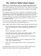
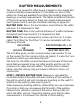
PIVOT Pivote SCRIBING NOTCHES (1" TO 5-1/2") MARKING EDGE Muescas para marcaciones (entre 1" y 5-1/2") Borde para marcado RAFTER SEAT CUT Indicación para corte de asiento Johnny Square ® 7" Professional Aluminum Rafter Angle Square with Rafter Square Instruction Book and Tables TOP CUTS/ HIP & VALLEY RAFTER SCALE Escala para cortes superiores y cortes en ángulo estilos Hip y Valley 1/4" SCALE (1" TO 3-1/2") Escala de 1/4" (entre 1" y 3-1/2") COMMON RAFTER SCALE Escala común para ángulos de vigas “T”-
The versatility and durability of Johnson’s “Johnny Square®” came to us from professional master carpenter Johnny Wong, an accomplished homebuilder with more than twenty-five years experience in the trades. Johnny’s crews were never satisfied with their rafter squares’ inability to allow for fast and accurate measurements for rip cuts. With more than three years of field testing, the “Johnny Square®” helps professionals like Johnny do more work in less time.
The Johnson® Rafter Angle Square Thank you for purchasing the Johnson® Rafter Angle Square. Since 1947 Johnson Level & Tool has been developing solutions to help professional tradesmen improve their work. Our products are trusted by professionals worldwide to work more accurately, more quickly and more reliably. This reference book will serve as a guide for providing basic rafter and angle layout information through various illustrations and tables.
SCRIBING NOTCHES (1" TO 5-1/2") PIVOT RAFTER SEAT CUT MARKING EDGE TOP CUTS/ HIP & VALLEY RAFTER SCALE 1/4" SCALE (1" TO 3-1/2") COMMON RAFTER SCALE “T”-BAR (FOOT) DEGREE SCALE/PROTRACTOR 2
TABLE OF CONTENTS Types of Rafters . . . . . . . . . . . . . . . . . . . . . . . . . 4 Rafter Measurements . . . . . . . . . . . . . . . . . . . . . 6 Inches to Feet Conversion (Table A) . . . . . . . . . . . . . 9 Common Rafters . . . . . . . . . . . . . . . . . . . . . . . . 9 Common Rafter Layout . . . . . . . . . . . . . . . . . . . . 12 Hip and Valley Rafters . . . . . . . . . . . . . .
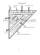
TYPES OF RAFTERS COMMON RAFTER: A rafter that runs perpendicular (90°) from the wall plate to the roof ridge when looking straight down at the roof. When looking from the side, its length forms the diagonal leg (or hypotenuse) of a right triangle that has its vertical leg equal to the rise and its horizontal leg equal to the run (see Figures 1, 3 and 8).
5 FIG. 1 Types of Rafters. All cuts on this roof can be made by using the number 8 (i.e. an 8 inch rise).
RAFTER MEASUREMENTS The use of our square for rafter layout is based on two simple and common building measurements: (1) the rafter run, and (2) the rafter rise. These are available from either the building blueprints, drawings, or actual measurements. The tables included in the back of this book are also based on these two simple measurements (see Figures 2 and 3, and also the tables starting on page 40). RAFTER RUN: Run is the horizontal or level distance the rafter will span. It is measured in feet.
FIG. 2 Rafter Runs and Rises for Different Style Roofs.
INCH RISE PER = FOOT RUN RISE X 12 RAFTER LENGTH = RUN RUN2 + RISE2 OR USE TABLES FIG. 3 The Common Rafter. Then the run is found by dividing in half the building width. When a ridge board is being used, deduct 1/2 its thickness from the run. STEP 2. OBTAIN ROOF RISE: Find the distance you wish the roof ridge to be above the wall (in feet) by measuring, calculating or obtaining it from the blueprints (see Figure 2).
TABLE A Change Inches to Feet 1" = .08' 2" = .16' 3" = .25' 4" = .33' 5" = .42' 6" = .50' 7" = .58' 8" = .67' 9" = .75' 10" = .83' 11" = .92' STEP 3. CALCULATE INCH RISE: For example, with the Run = 13' 0" and Rise = 8' 9". First convert the rise to feet in decimal form, using TABLE A. Therefore, the Rise = 8.75'. Now, using the formula for the “Inch Rise”: 8.75' x 12 Inch Rise = = 8.08 in/ft. Run 13' Round off the Inch Rise to the nearest inch.
FIG. 4 Common Rafter Layout. length. For our rafter we get 15' 7-1/2". This is the rafter length from the top cut to the seat plumb mark (see Figure 4). NOTE: For a run greater than that given in the tables, simply add any two runs that will equal the run desired. Then find the lengths for those two rafters and add them together. For example, say that your run is 38', add the length for a 18' run and the length for a 20' run together. Or add a 15' run’s length and a 23' run’s length together.
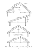
FIG. 5 Suggested Eave Construction.
a tail run of 1' 9". In the same “Common” table as used above, for an 8” rise, we find: 1' Run = 1' 2-1/2" 9" Run = 10-7/8" 1' 9" Tail = 2' 1-3/8" COMMON RAFTER LUMBER LENGTH: To obtain the total length of the rafter, an allowance for the bottom plumb cut must now be made (see Figure 4). This allowance can be obtained by using the tables. In our example, let us use a 2 x 6 piece of lumber which will give us a depth of 5 1/2 inches.
FIG. 6 Top Plumb Cut of a Common Rafter.
FIG. 7A Seat Notch or Bird’s Mouth Layout. FIG. 7B Seat Notch or Bird’s Mouth Layout. building. Now line up the dashed line (above the 80° increment on the square) with the plumb mark (see Figure 7A & 7B). Draw the horizontal seat mark, a perpendicular line, along the bottom of square. Never notch more than halfway through the rafter and make all seat notches the same depth. STEP 3.
as you did in Step 1. You may wish to leave the tails long until all the rafters are in place, so that you can mark the ends to a line and then cut. NOTE: The top and bottom cuts on the rake board are also done in the same way as a common rafter but the distance from the top cut to the bottom cut is the rake board length.
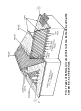
HIP-VAL LENGTH: Use the table on page 47 to obtain the hip or valley rafter length (continuing the 8 Inch Rise example from page 9, Step 3). In our example an 8 Inch Rise is used, therefore find the column headed “Run Ft.” and locate 13'. To the right read the column headed “Hip or Val. Rafter Length” and find a length of 20' 3-7/8" (see Figures 8, 9, 10, 12 and 13). FIG. 9 View of Hip Rafter Layout.
FIG. 10 Hip Rafter Layout. TAIL OR EAVE LENGTH: Use the same procedure as you did for the common rafter but remember to use the HipVal column. Again we have in our example a tail 1’ 9” long, thus giving us: 1' Run = 1' 6-3/4" 9" Run = 14-1/8" 1' 9" Tail = 2' 8-7/8" NOTE: If a miter is desired, add for hip or val miter allowance from the tables (see Figures 10 and 13). HIP-VAL LUMBER LENGTH: Add an allowance for a bottom plumb cut and, if used, a miter.
and a miter allowance (using a 1 1/2" actual rafter thickness) we get: RAFTER LENGTH = 20' 3-7/8" TAIL LENGTH = 2' 8-7/8" BOTTOM PLUMB ALLOW. = 3-11/16" MITER ALLOWANCE = 7/8" LUMBER LENGTH = 23' 5-5/16" NOTE: Only add miter allowances if they are used. HIP RAFTER LAYOUT STEP 1. TOP PLUMB CUT: The square is used in the same manner as in Step 1 of the common rafter top plumb cut. But now, read the Inch-Rise on the Hip-Val scale instead.
used, make another plumb mark on the other side of the rafter just opposite of the bottom plumb mark (see Figure 10). STEP 4. CUTTING HIP RAFTER PATTERN: With your saw set at 45°, cut the top plumb cut, making sure the top bevels are opposite for opposite rafters. Setting the saw at 45° automatically gives the plumb cut and the side cut bevel. Make bottom plumb cut on a 45° angle if miter is used. If a bevel is not needed, set saw at 90°. The seat notch is made with the saw at 90° (see Figures 9 and 10).
Now mark across top of ridge (as shown). This mark will be the center of the two intersecting hips. If a common rafter is to be used, the ridge will be cut off at this mark and the common rafter butted up against it (see Figure 9). If no common rafter will be used, cut the ridge about 2" longer. This will allow you to nail through the ridge into the hip. VALLEY RAFTER LAYOUT STEP 1. TOP PLUMB CUT: Using the Hip-Val scale again, make the top plumb mark in the usual way.
FIG. 12 View of Valley Rafter Layout. STEP 3. BOTTOM OR TAIL PLUMB CUT: Measure down the top of the valley rafter from the SEAT PLUMB MARK and mark the tail length (in our example: 2' 8-7/8"). Be sure to add the miter allowance in the measurement, if used (see Figure 13). Make the bottom plumb mark with the square in the normal manner. STEP 4. RAFTER PATTERN CUTS: To make the top and bottom cuts, tilt the saw at 45° (see Figure 13). Also make the seat miter cuts.
FIG. 13 Valley Rafter Layout. JACK RAFTERS JACK RAFTER LENGTH: The Jack Rafter Tables are different than those for the other rafters. The table lists, in the first column, the varying center-to-center spacing of the jack rafters. Then in the second column is the difference in length from one jack to the next (see Figures 14 and 15). This difference in length is to be added to or subtracted from the rafter length as you progress from jack to jack (using the spacing selected).
FIG. 14 Top View of Hip Jack Rafter Spacing.
FIG. 15 Top View of Valley Jack Rafter Spacing. distance from the edge of the last common rafter to the intersection of the hip and ridge, or the valley and top plate (for a valley jack). This measurement is called (P) in Figures 14 and 15. Now subtract the measurement (P) from the spacing you are using (W). The result (W – P) is the distance from the intersection of the hip and ridge to the first hip jack or the plate corner to the first valley jack.
COMMON RAFTER LENGTH = 15' 7-1/2" SUBTRACT (W – P) FROM TABLE = 1' 2-3/8" FIRST HIP JACK RAFTER LENGTH = 14' 5-1/8" The tail length must now be added to this length. For all remaining jacks, subtract the full spacing (W).
The common scale on the square is used for all jack rafters. Whenever a jack rafter rests against a hip or valley rafter, mark a plumb cut, and then cut at a 45° along the mark. This will give both the side cut and the plumb cut. Angles should be checked for direction before cuts are made. See Figures 11 and 14 for the center common rafter at the end of the ridge. DORMER RAFTERS Sometimes when adding a room or remodeling, it is easier to build a valley on top of the main roof.
roof. For a pitched roof, use the angle scale and make your mark next to the angle that is the result of the roof inch rise angle minus the overhang inch rise angle. DEGREE SCALE With the degree scale on our square, any angle can be found on a board. Figure 16 shows a couple of examples. To find an obtuse angle, for example 105°, put the pivot point on the mark where the cut is to be made. Lay the square so that the “T” bar is held tight against the board and draw a perpendicular line across the board.
STAIR LAYOUT EXAMPLE With our square, stair layout can be done simply and efficiently. The layout can be done without hours of calculations. Basic math and the use of a calculator with a square root function are all that are needed. STEP 1. FIND STEP MEASUREMENTS: We start with the total rise (see Figure 17) to find the number of steps required. If the rise is not known, measure the vertical distance between the lower finished floor and the upper one.
1. Find the approximate number of steps with the following formula: TOTAL RISE (inches) APPROXIMATE NO. OF STEPS = 7" For example, let’s assume a 8' 6" rise = 102” 102" APPROXIMATE NO. OF STEPS = 7" = 14.57" NOW THE ACTUAL NUMBER OF STEPS WOULD BE THE WHOLE NUMBER, IGNORING ANY FRACTION, i.e., 14 STEPS. Next, find the actual step rise by using the following computation. TOTAL RISE (inches) ACTUAL STEP RISE = NO. OF STEPS In our example: 102" 14 ACTUAL STEP RISE = 7.29" 2.
The ideal inch rise is 7 or 8 (or 30° to 35°) but may be from a 5-inch rise to a 14-inch rise depending on the circumstances. The step rise or run may be modified if the run becomes impractical or if the minimum head room is under 6 1/2 ft. Check the head room by measuring down along a plumb line dropped from the lowest ceiling point to where the tread beneath would be. To find the tread height, count the number of steps necessary to get under the plumb line and then multiply by the step rise.
STEP 2. LAYOUT STRINGER: First, find the step incline length (see Figure 18) by using the following formula: STEP INCLINE = (STEP RISE)2 + (STEP RUN)2 In our example: STEP RISE = 7.29 STEP RUN = 10.21 USING THE FOLLOWING INCLINE FORMULA: STEP INCLINE = = = = NOTE: The symbol (7.29)2 + (10.21)2 (53.14) + (104.24) 157.38 12.545 is the square root symbol.
FIG. 19 Step Layout. Now, draw the bottom plumb line using your inch rise on the common scale of the square, exactly as you did for the common rafter (see Figures 18 and 19). If you wish to conserve wood, adjust the bottom plumb line so that its length is equal to the step rise. Next draw the bottom floor line by measuring down the bottom plumb line the distance of the step rise minus the tread thickness. In our example, with a 1" tread; 7.29" minus 1.00" giving you 6.29", or 6 5/16".
The outside step corners should now be marked off (again see Figure 18). Starting from the bottom plumb line, measure up along the top edge of the stringer the distance of a step incline. Repeat this for each step corner, until you’ve reached the stringer incline length. Make another step incline mark for a top plumb line. Now draw the riser plumb lines for all the steps, using the square as you did for the bottom plumb line. Finally, draw a top plumb line.
TABLE B Change Decimals to Fractions .06" = 1/16" .56" = 9/16" .13" = 1/8" .63" = 5/8" .19" = 3/16" .69" = 11/16" .25" = 1/4" .75" = 3/4" .31" = 5/16" .81" = 13/16" .38" = 3/8" .88" = 7/8" .44" = 7/16" .94" = 15/16" .50" = 1/2" SOLAR PANEL SUPPORT EXAMPLE Let us build a rafter support for a series of flat plate collectors on a south-facing 8-inch rise roof. STEP 1.
FIG. 20 A Rafter Support Structure for Solar Panels. Now find the support rafter rise and run by using the tables somewhat in reverse from the way you have done so far. First find the proper table for your support rafter inch rise and locate your length under the common rafter length column (note: you may have to refer to both the Run (ft.) column plus the Run (inch) column in referring to the correct length).
support rafter length. To begin with, we find a 2' run having a 3' 9" length. This then leaves a 5" length which results in an approximation of a 2-11/16" run. If needed, approximating can be done with the following equation, if desired: ( Rh x ( Rm = Lm – Ll Lh – Lm )) + Rl Lm – Ll ) 1.00 + ( Lh – Lm Where R = run, L = length, l = low, m = middle, h = high. In our example: 5.00 – 4.63 ) ) + 2.50 5.63 – 5.00 Rm = 1.00 + 5.00 – 4.63 ( 5.63 – 5.00 = 2.69 = 2-11/16" ( 3.
FIG. 21 Rafter Layout For A Solar Panel. and the front overhang rafter thickness. The roof run between points A and B is found by: ROOF RISE (in.) x 12 ROOF RUN (in.) = INCH RISE 42.25" x 12 8 inch rise 63.
From this we can get the overhang rafter length, noting that we are using 2 x 6 rafters giving a thickness of 1-1/2": or in feet: ROOF RUN BETWEEN A & B – SUPPORT RAFTER RUN – FRONT OVERHANG THICKNESS = OVERHANG RAFTER LENGTH 63.37" – 26.69" – 1.50" = 35.18" = 2' 11 3/16" Lastly we need to find the pitched rafter length, the rafter above the horizontal overhang rafter. In our example, the pitched rafter length will equal the support rafter length (i.e., 50"). STEP 2.
The pitched rafter top cut layout (at point C in Figure 21) is the same as the support rafter bottom cut layout (at point A). For the pitched rafter bottom cut layout (at point D) the following equation is used: BOTTOM ANGLE = SUPPORT ANGLE + ( 2 x ROOF ANGLE ) – 90° In our example: = 57 3/4° + (2 x 33 3/4°) – 90° = 35 1/4° Use this equation when the pitched rafter length equals the support rafter length.
40
41
42
43
44
45
46
47
48
49
50
51
52
53
54
55
56
57
58
59
60
61
62
63
For additional copies of this instruction manual go to www.johnsonlevel.com The manufacturer of this product is not responsible for any errors or omissions that may occur in the production of this reference guide.
PIVOT Pivote SCRIBING NOTCHES (1" TO 5-1/2") MARKING EDGE Muescas para marcaciones (entre 1" y 5-1/2") Borde para marcado RAFTER SEAT CUT Indicación para corte de asiento Johnny Square ® 7" Professional Aluminum Rafter Angle Square with Rafter Square Instruction Book and Tables TOP CUTS/ HIP & VALLEY RAFTER SCALE Escala para cortes superiores y cortes en ángulo estilos Hip y Valley 1/4" SCALE (1" TO 3-1/2") Escala de 1/4" (entre 1" y 3-1/2") COMMON RAFTER SCALE Escala común para ángulos de vigas “T”-