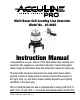
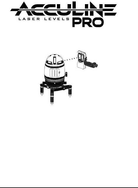
™ Multi-Beam Self-Leveling Line Generator Model No. 40-6660 Instruction Manual Congratulations on your choice of this Multi-Beam Self-Leveling Line Generator. We suggest you read this instruction manual thoroughly before using the instrument. Save this instruction manual for future use. This tool emits five laser beams and one down plumb beam which projects a series of visible points on surfaces around the product (i.e. left, right, front, up, and down).
Table of Contents 1. Kit Contents 2. Features and Functions 3. Safety Instructions 4. Location/Content of Warning Labels 5. Location of Parts/Components 6. Operating Instructions 7. Using the Accessories 8. 9. 10. 11. 12. 13. 14. Self-Check and Calibration Technical Specifications Application Demonstrations Care and Handling Product Warranty Product Registration Accessories 1.
2. Features and Functions • Switchable between continuous laser state and pulse laser beam (for use with detector) • Able to project four laser cross lines and one laser point (and a down plumb) • Self-leveling compensation system. • Laser flashes and sounds audible alarm when product beyond leveling range. • Able to individually project one horizontal line, or three vertical lines that are perpendicular to each other, with one red plumbdown point.
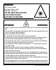
DANGER! Class IIIa Laser Product Max. Power Output: ≤ 5mW Wavelength: 625-645nm THIS TOOL EMITS LASER RADIATION. DO NOT STARE INTO BEAM. AVOID DIRECT EYE EXPOSURE. ATTENTION IMPORTANT • Read all instructions prior to operating this laser tool. Do not remove any labels from tool. • Use of controls or performance of procedures other than those specified herein may result in hazardous radiation exposure. • Do not stare directly at the laser beam.
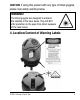
CAUTION: If using this product with any type of tinted goggles, please note safety warning below. WARNING! The tinted goggles are designed to enhance the visibility of the laser beam. They DO NOT offer protection to the eyes from direct exposure of the laser beam. 4.
5.
6. Operating Instructions IMPORTANT: It is the responsibility of the user to verify the calibration of the instrument before each use. Battery Installation Note: Always check to be sure that the on/off switch is in the off position before removing and replacing batteries. 1. Open the battery box and put in rechargeable battery pack. Please pay attention to polarity. 2. Indicator lamp blinking means low voltage. Charge the rechargeable battery pack before initial use.
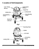
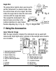
2. Activate the horizontal line H, vertical lines V1 and V2, and plumbdown point by pressing the corresponding keys on the operating panel (Fig. 3). 1. Horizontal Line H Button 2. Vertical Line V1Button 3. Modulation Switching P Button 4. Power Indicator Lamp 5. Vertical Line V2 Button 6. Modulation Switching Indicator Lamp 3. When the power indicator lamp is lit, this means the laser is turned on. When the blinking power indicator lamp is lit, this means low battery voltage. 4.
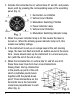
6. Adjust the screws on the three legs of the base to center the top bubble, which will achieve the higher accuracy (Fig. 5). Power-Off Set the locking knob to LOCK position, and the instrument is powered off (Fig. 6). Screw Bubble Centering Fig. 5 Fig. 6 Locking Position Note: The locking knob must be set to LOCK position when the user needs to move the instrument or packed into the case. If the alarms sounds when you move the unit, it means the locking screw is not locked. Please make sure to lock it.
Angle Dial The angle dial is helpful when users need to set the instrument to a desired angle. Have the vertical lines aim at an object, and then rotate the angle dial to make the zero scale coincide with the angle dial scale. Then adjust the instrument to the desired angle according to the method described in Laser Output Position Adjusting (Fig. 8, Fig. 9). Fig. 9 Angle Fine Adjusting Screw Fig. 8 Dial Angle Dial Indication 7.
LCD Indicating Note 1. Power 2. Low Voltage 3. Detection 4. Sound 5. Detected Position Operation Instruction 1. Battery Installation Open the battery door, and put in one 9V battery according to the polarity shown inside. Then snap the battery door back. Note: • Take the battery out when the unit is not in use for a long time. • Replace the battery when indicator shows low battery. • Used (discharged) batteries are hazardous waste and should be disposed of properly 2.
B. Detecting the horizontal laser signal: Put the detector in a vertical position (observe the horizontal indicating bubble) with the detecting window facing the unit to receive the laser signal. A downward arrow shown on LCD plus a lit red lamp means the laser signal is below the detector. An Upward arrow plus a yellow lit lamp means the laser signal is above the detector. A middle sign plus a lit green lamp means the laser signal is centered.
3. Sound Function Pressing the sound key under power-on status will switch the unit between sound status and silent status, with the sound sign indication on LCD. Sound Silence Under the status with sound function on: • If the laser signal is on the top (left) side, then the detector will give single short alarm. • If the laser signal is on the bottom (right) side, then the detector will give double short alarm. • If the laser signal is on the middle, then the detector will keep long alarm.
Technical Specifications Detecting Distance ≥164 ft (50m) 0 ≥98 ft (30m) 45 Detecting Frequency 8KHz-12KHz Detecting Accuracy 0.019" ≤ 49 ft. (0.5mm ≤15m) 0.039" ≤ 114 ft. (1mm ≤35m) 0.059" ≥ 114 ft. (1.5mm ≥35m) Timed Power-off 6 minutes Working Voltage DC 9V Sound Function: Single short alarm double short alarm long alarm LCD Upward arrow downward arrow centered sign LED Indication Up, middle, down Size 5.905" x 2.992" x 1.142" (150 x 76 x 29mm) Weight 0.386 lb.
Instrument Usage Tripod Usage The instrument can be used either directly on floor or on tripod. If operating with tripod, users should first screw the connecting board into the thread on the instrument bottom, and set it up on tripod Tripodic Base Usage 1. Connect the instrument with tripodic base through 5/8” center thread, and then the plumb-down point function become available for use. 2. Tripodic base can be folded used. 3. The legs could be adjusted in length Laser Glasses Usage 1.
8. Self-Check and Calibration Horizontal Laser Line Accuracy Self-Check 1. Find a wall and set up the instrument at 16 ft. (5m) away from the wall. 2. Unlock the instrument and switch on the laser line H, V1, V2 by pressing the button H, V1,V2. 3. Rotate the instrument horizontally to have V1 face against the wall, and mark its intersection with H as point A (Fig. 11-1). 4. Turn the instrument Fig. 11-2 to have V2 coincide Fig. 11-1 with point A. 5. Measure the distance e between H and point A. 6. If e >0.
6. Observe whether the downside of V1 coincides with the standard plumb line or not. If not, and the deviation exceeds 0.039" (1mm), then V1 line's vertical accuracy e is beyond tolerance (Fig.12). NOTE: During the observation, make sure that your viewing is against the laser line and the standard plumb line. 7. Follow the same method to check the accuracy of V2. 8. If the self-checked accuracy is beyond tolerance, reference section 12 of this document. Plummet V1 9.
10.
11. Care and Handling • This laser unit is a precision tool that must be handled with care. exposing unit to shock vibrations and extreme temperatures. • Before moving or transporting the unit, make sure that the unit is turned off and in the locked position. Failure to lock before transport or storage may cause damage to the units inner mechanism and void warranty.
Authorization (RMA) number for return to an authorized service center. Proof of purchase is required. NOTE: The user is responsible for the proper use and care of the product. It is the responsibility of the user to verify the calibration of the instrument before each use. For further assistance, or if you experience problems with this product that are not addressed in this instruction manual, please contact our Customer Service Department. In the U.S.
14. Accessories AccuLine Pro™ accessories are available for purchase through authorized AccuLine Pro dealers. Use of non-AccuLine Pro accessories will void any applicable limited warranty and there will be NO WARRANTY. If you need any assistance in locating any accessories, please contact our Customer Service Department. In the U.S., contact Johnson Level & Tool’s Customer Service Department at 800-563-8553. In Canada, contact Johnson Level & Tool’s Customer Service Department at 800-346-6682.