Self-Leveling Cross-Line Laser Level with GreenBrite® Technology Model No. 40-6640 Instruction Manual Congratulations on your choice of this Self-Leveling Cross-Line Laser Level. We suggest you read this instruction manual thoroughly before using the instrument. Save this instruction manual for future use. This is a Class IIIa laser tool and is manufactured to comply with CFR 21, parts 1040 .10 and 1040 .11 as well as international safety rule IEC 285.
Table of Contents 1. Kit Contents 2. Features and Functions 3. Safety Instructions 4. Location/Content of Warning Labels 5. Location of Parts/Components 6. Operating Instructions 7. Using the Product 8. 9. 10. 11. 12. 13. 14. Self-Check and Calibration Technical Specifications Application Demonstrations Care and Handling Product Warranty Product Registration Accessories 1.
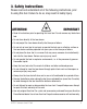
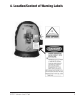
. Safety Instructions Please read and understand all of the following instructions, prior to using this tool. Failure to do so, may result in bodily injury. ATTENTION IMPORTANT • Read all instructions prior to operating this laser tool. Do not remove any labels from tool. • Do not stare directly at the laser beam. • Do not project the laser beam directly into the eyes of others.
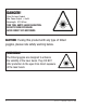
DANGER! Class IIIa Laser Product Max. Power Output: ≤ 5mW Wavelength: 522-542nm THIS TOOL EMITS LASER RADIATION. DO NOT STARE INTO BEAM. AVOID DIRECT EYE EXPOSURE. CAUTION: If using this product with any type of tinted goggles, please note safety warning below. WARNING! The tinted goggles are designed to enhance the visibility of the laser beam. They DO NOT offer protection to the eyes from direct exposure of the laser beam.
4.
5.
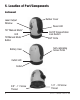
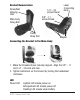
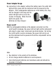
Bracket Nomenclature Screw/Nail Hanging Hole 1/4" - 20 screw thread Laser Connecting Knob 5/8" - 11 screw thread Main-body Fixing Bolt Fixing Strap Slot Magnet Connecting the Bracket to the Main-Body 1. Make the threaded holes mutually aligned. Align the 5/8” - 11 and 1/4” - 20 knob and hole. 2. Tighten instrument on the bracket by turning the handwheel clockwise.
Outlet LED Extinguished LED means no external power Green LED means connected to external power or battery is fully charged Red LED means charging the battery Tilt Manual Mode LED Extinguished LED means the normal working state, and the laser line will flash if out of the self-leveling range Lighted LED means the laser is in the Tilt “Manual Mode”. This turns off the out of level indicators (sound and flash) and allows the operator to tilt the unit for extreme slope 6.
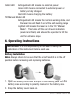
Power Adapter Usage By connecting to the adapter, without the battery pack, the outlet LED light will turn green and the instrument will be powered by the adapter. If the rechargeable batteries are in the battery box, they will be charged in this way and the outlet LED light will be red in the course of charging. When the LED light turns green, the batteries are fully charged.
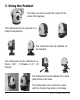
7. Using the Product The laser can turn around the center of the scale 360 degrees. The instrument can be placed on a platform separately. The instrument can be installed on the bracket. The instrument can be installed on a tripod. (5/8” - 11 thread or 1/4” - 20 thread) The instrument can be attached to a steel plate while on its base. The instrument can be fixed to a pipe with the fixing strap while on its base.
8. Self-Check and Calibration IMPORTANT: It is the responsibility of the user to verify the calibration of the instrument before each use. 1. Set the instrument on a level flat head tripod centered between two walls (marked 1 & 2) approximately 15 feet apart. (See fig. 1). 2. Point the instrument directly at wall 1. Turn the laser on and mark the intersection of the beams as point A. 3. Turn the instrument 180 degrees so that the laser is pointed directly at wall 2.
Calibration Re-calibration can be performed as described below. 1. Use a level to mark a horizontal reference line on the wall. 2. Power on the unit to compare the projected horizontal line with the reference line. Figure 1 Figure 2 3. If the projected laser line is tilted, power off the unit and lock the compensator. Screw off the calibration portal screw (figure 1) Use a 3mm hex head wrench to calibrate the unit through its side calibration hole.
9. Technical Specifications Laser Wavelength Laser Classification Maximum Power Output Accuracy Interior Range Self-Leveling Range Power Supply Battery Life Dimensions Weight Working Temperature Center Screw Thread IP Protection Class ©2007 Johnson Level & Tool 532nm±10 Class IIIa ≤5mW ±1/8"/35 ft. (±3mm/10m) Up to 200 ft. (60m) depending upon light conditions ± 5° Rechargeable battery pack or 6V adapter (included) Approx. battery life 20 hours continuous use 3 7/8" x 4 1/4" x 5 1/8" (98x110x130mm) 1.
10.
11. Care and Handling • This laser unit is a precision tool that must be handled with care. • Avoid exposing unit to shock vibrations and extreme temperatures. • Before moving or transporting the unit, make sure that the unit is turned off and is in the locked position. Failure to lock before transport or storage may cause damage to the units inner mechanisms and void warranty.
12. Product Warranty Johnson Level & Tool offers a one year limited warranty on each its products. You can obtain a copy of the limited warranty for a Johnson Level & Tool product by contacting Johnson Level & Tool's Customer Service Department as provided below or by visiting us online at www.johnsonlevel.com. The limited warranty for each product contains various limitations and exclusions. Do not return this product to the store/retailer or place of purchase.
13. Product Registration Enclosed with this instruction manual you will find a warranty card to be completed for product warranty registration. Product warranty registration can also be completed online at our web site www.johnsonlevel.com. You will need to locate the serial number for your product that is located on the bottom of the unit.
14. Accessories AccuLine Pro™ accessories are available for purchase through authorized AccuLine Pro dealers. Use of non-AccuLine Pro accessories will void any applicable limited warranty and there will be NO WARRANTY. If you need any assistance in locating any accessories, please contact our Customer Service Department. In the U.S., contact Johnson Level & Tool’s Customer Service Department at 800-563-8553. In Canada, contact Johnson Level & Tool’s Customer Service Department at 800-346-6682.
©2007 Johnson Level & Tool 19
©2007 Johnson Level & Tool