™ Automatic-Leveling Horizontal Rotary Laser Level Model No. 40-6535 Instruction Manual Congratulations on your choice of this Automatic-Leveling Horizontal Rotary Laser Level. We suggest you read this instruction manual thoroughly before using the instrument. Save this instruction manual for future use. This is a Class IIIa laser tool and is manufactured to comply with CFR 21, parts 1040 .10 and 1040 .11 as well as international safety rule IEC 285.
Table of Contents 1. Kit Contents 2. Features and Functions 3. Safety Instructions 4. Location/Content of Warning Labels 5. Location of Parts/Components 6. Operating Instructions 7. Using the Product 8. Accuracy Self-Check 9. Technical Specifications 10. Application Demonstrations 11. Care and Handling 12. Product Warranty 13. Product Registration 14. Accessories 1. Kit Contents Description Model No.
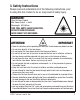
. Safety Instructions Please read and understand all of the following instructions, prior to using this tool. Failure to do so, may result in bodily injury. DANGER! Class IIIa Laser Product Max. Power Output: ≤ 5mW Wavelength: 625-645nm THIS TOOL EMITS LASER RADIATION. DO NOT STARE INTO BEAM. AVOID DIRECT EYE EXPOSURE. ATTENTION IMPORTANT • Read all instructions prior to operating this laser tool. Do not remove any labels from tool. • Do not stare directly at the laser beam.
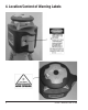
. Location/Content of Warning Labels 4 ©2007 Johnson Level & Tool
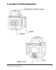
. Location of Part/Components Rotating laser emitting window Handle Keypad Battery Cover ©2007 Johnson Level & Tool DC 6V 5
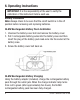
. Operating Instructions IMPORTANT: It is the responsibility of the user to verify the calibration of the instrument before each use. Battery Installation Note: Always check to be sure that the on/off switch is in the off position before removing and replacing batteries. Ni-MH Rechargeable Battery Pack Installation 1. Unscrew the battery cover bolt and remove the battery cover. 2.
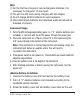
Note: (1) For the first two charges of new rechargeable batteries, it is necessary to charge for 12 plus hours. (2) The unit can still work during charging with the adapter. (3) Do not charge alkaline batteries to avoid explosion. (4) Used (discharged) batteries are hazardous waste and should be disposed of properly. Instrument Usage 1. Put in Ni-MH rechargeable battery pack, or 4 “C” alkaline batteries (not included), or connect with the 6V DC power through the power jack. 2.
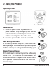
7. Using the Product Operating Panel Instrument Panel Remote Control Panel Power On/Off 1. Press the power button to power on. The power indicator lamp will light up and then the instrument will automatically level itself, with rotation occurring once the unit is level. 2. Press the power button again to power off. Low Battery Indication If the battery indicator lamp is lit, this means low battery voltage. To ensure normal operation, replace batteries or charge the rechargeable Ni-MH battery pack.
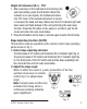
Height of Instrument (H.I.) - TILT 1. After powering on the instrument and entering into auto-level status, press the tilt button. When the indicator is on (see figure), the instrument enters into TILT mode. If the leveled instrument is moved or bumped, the head will stop rotation and the TILT indicator light and laser beam will flash instead of the unit performing the auto-level function. Press the tilt button on the panel or remote to quit the tilt mode and enter into auto-level status. 2.
Adjust the inclination extent of the slope Pressing the up/down arrow keys on the remote control, will adjust the inclination of the instrument slope. A single press will cause a slight adjustment and a continuous presses will cause a quick adjustment. If laser is taken past its slope range (±8º), the laser will deliver an audible alarm and the laser beam will flash and stop rotating. Sleep Mode 1. The first press of the POWER button on the remote control (fig.4) will make the instrument enter sleep mode.
Detector Usage 1. Product Description A laser detector is an indispensable accessory when using this rotary laser level. The main function of the detector is to locate the position of laser signals transmitted by rotary lasers. This detection quickly and precisely provides the user with the horizontal reference. This product features a high level of sensitivity, a double-faced display, low power consumption, reliability and easy use. 2.
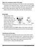
8. Self-Check and Calibration IMPORTANT: It is the responsibility of the user to verify the calibration of the instrument before each use. The instrument must be self-checked before operation. If the accuracy is found beyond tolerance, user can make some adjustment according to directions as follows. X-Direction Accuracy Self-Check 1. For clarity, we define the direction of handle as Y-direction, and another direction as X-direction 2.
X-direction self-check with the same method as Y-direction self-check, and mark point C and point D by turns. 7. If point C and point D are within 1/32” at 50’, the accuracy is within tolerance. Otherwise reference section 12 of this document. Enter self-calibration In power off status, press the power and the tilt buttons of the laser unit simultaneously. Then let go of the power button while still pressing the tilt button.
Adjust laser beam to reference position Press the up/down arrow buttons on the remote control to adjust the laser beam to reference position. Confirm calibration value Press ‘ENT’ button on the remote control to confirm self-calibration value. The X direction self-calibration indicator light will extinguish after pressing this button.
Confirm calibration value Press ‘ENT’ button on the remote control to confirm self-calibration value. The Y direction self-calibration indicator light will extinguish after pressing this button. Note: In order to make the calibration effective, you must power off the instrument after the calibration, and then power it on again. Y-axis accuracy check is a necessity after X-axis calibration, and X-axis accuracy check is also a necessity after Y-axis calibration.
10.
11. Care and Handling • This laser unit is a precision tool that must be handled with care. exposing unit to shock vibrations and extreme temperatures. • Before moving or transporting the unit, make sure that the unit is turned off. • Remove the batteries when storing the unit for an extended time (more than three months) to avoid damage to the unit should the batteries deteriorate. • Always store the unit in its case when not in use. • Avoid getting the unit wet.
12. Product Warranty Johnson Level & Tool offers a one year limited warranty on each its products. You can obtain a copy of the limited warranty for a Johnson Level & Tool product by contacting Johnson Level & Tool's Customer Service Department as provided below or by visiting us online at www.johnsonlevel.com. The limited warranty for each product contains various limitations and exclusions. Do not return this product to the store/retailer or place of purchase.
13. Product Registration Enclosed with this instruction manual you will find a warranty card to be completed for product warranty registration. Product warranty registration can also be completed online at our web site www.johnsonlevel.com. You will need to locate the serial number for your product that is located on the bottom of the unit.
©2007 Johnson Level & Tool