™ Self-Leveling Rotary Laser Level Model Nos. 40-6525 and 40-6530 Instruction Manual Congratulations on your choice of this Self-Leveling Rotary Laser Level. We suggest you read this instruction manual thoroughly before using the instrument. Save this instruction manual for future use. This is a Class IIIa laser tool and is manufactured to comply with CFR 21, parts 1040.10 and 1040.11 as well as international safety rule IEC 285.
Table of Contents 1. Kit Contents 2. Features and Functions 3. Safety Instructions 4. Location/Content of Warning Labels 5. Location of Parts/Components 6. Operating Instructions 7. Using the Product 8. Accuracy Self-Check 9. Technical Specifications 10. Application Demonstrations 11. Care and Handling 12. Product Warranty 13. Product Registration 14. Accessories 1. Kit Contents For Model No.
2. Features and Functions • Magnetic dampening compensation system. • Laser sounds alarm when outside its self-leveling range or the compensator is not locked when the laser is placed inside its case. • Projects a horizontal rotating plane. • Projects a vertical rotating plane with a 90º split beam. • Optional scan feature, from small to large, provides user a visible chalk line. • Adjustable scan direction. • Adjustable rotation speed. • Works with both alkaline batteries and rechargeable battery pack.
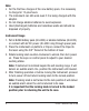
ATTENTION IMPORTANT • Read all instructions prior to operating this laser tool. Do not remove any labels from tool. • Do not stare directly at the laser beam. • Do not project the laser beam directly into the eyes of others. • Do not set up laser tool at eye level or operate the tool near a reflective surface as the laser beam could be projected into your eyes or into the eyes of others. • Do not place the laser tool in a manner that may cause someone to unintentionally look into the laser beam.
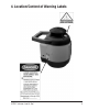
4.
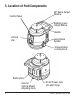
5.
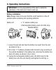
6. Operating Instructions IMPORTANT: It is the responsibility of the user to verify the calibration of the instrument before each use. Battery Installation Note: Always check to be sure that the on/off switch is in the off position before removing and replacing batteries. Battery kit: • “C” alkaline battery box • Rechargeable battery-pack (40-6530 only) Alkaline Battery Box Bolt 1. Loosen the set-bolt and take the battery box apart from the unit, as shown in fig. a. 2.
Note: • For the first two charges of the new battery pack, it is necessary to charge for 12-plus hours. • The instrument can still work even if it is being charged with the adapter. • Do not charge alkaline batteries to avoid explosion. • Used (discharged) batteries are hazardous waste and should be disposed of properly. Instrument Usage 1. Put in Ni-MH battery pack (40-6530) or alkaline batteries (40-6525), or connect with 6V DC power (40-6530 only) through power jack. 2.
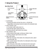
7. Using the Product Operating Panel Scan Indicator Light Scan Mode Button Down/Clockwise Button Power Indicator Light On/Off Button Up/Counterclockwise Button 1. On/Off Button • Pressing the button will turn the unit on / off after the transportation lock has been turned to unlock in the horizontal mode. 2. Power Indicator Light • Lit indicator light means power-on. • Unlit indicator light means power-off. • Flashing indicator light means low voltage. 3.
5. Up-Counterclockwise/Down-Clockwise button In rotation mode • Press up to increase rotation speed • Press down to decrease rotation speed In scan mode • Press down to make the scan line rotate clockwise • Press up to make the scan line rotate counter-clockwise Usage for vertical application IMPORTANT: Keep “Locking Knob” in the “Locked” position. 1. Install batteries/battery pack as previously discussed. 2. Insert the “Adjusting Knob” into the back of the laser and attach the vertical mount.
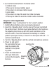
Detector Usage (included in Model No. 40-6530 only) 1. Technical Specifications Detecting accuracy Fine ±0.039" (±1mm) Coarse ±0.098" (±2.5mm) Turn-off time 5 minutes Operating voltage DC9V Size 6-3/4" x 3" x 1" (0.266 x 0.118 x 0.029mm) Weight 0.55 Ibs (0.249 Kg) Dust and rain resistant Backlit Screen Double sides display Horn for beam location 2. Components (a) Structure 1. Front Display window 2. Level vial 3. Coarse/Fine detection button 4. Horn 5. Power button 6. Horn button 7. Back light button 8.
(b) Display 1. Power symbol 2. Low battery symbol 3. Coarse/Fine detection symbol 4. Horn symbol 5. Detecting position symbol 3. Operation Guide (a) Installation of battery • Open the battery-box cap • Put the 9V battery into the battery-box. Please note the polarity. Then close the battery-box cap. Note: Take the battery out of the detector if it will not be used for a long time. (b) Turn on/off • Press the power button. When Power symbol is displayed, the detector is ready for coarse detection.
(c) Using the detector bracket 1. clamp bolt 2. quick release button 3. detector/bracket attachment screw (d) Detection 1. Coarse detection • Aim the receiving window at the rotating laser instrument. Loosen the clamp bolt and move the detector up and down to receive the laser signals transmitted by the rotating laser. • When the detector displays like Fig. (A), move the detector slightly down as indicated by the arrow. When it displays like Fig. (B), move it slightly up as indicated by the arrow.
2. Fine detection 1. power symbol 2. fine detection symbol • Press the coarse/fine detection button. The detector is ready for fine detection. • Move the instrument up and down like the coarse detection procedure. • When the instrument displays as shown in the figure, it is level with the laser beam. • Tighten the clamp bolt and mark the position of the object on the rabbet. (e) Sound function • Press the horn button. The horn symbol is displayed and it is ready for the sound function.
8. Self-Check and Calibration IMPORTANT: It is the responsibility of the user to verify the calibration of the instrument before each use. 50’ X-Direction Accuracy Self-Check 1. For clarity, we define the direction of handle as X-direction, and another direction as Y-direction 2. Place the unit on a platform that is 50’ away from a wall indoors, with the handle facing the wall head-on. Unlock the unit and set to low speed. 3. Mark on the wall where the beam hits the wall and mark that as A.
6. Turn the instrument by 90° and place it on the platform, with the operating panel facing you. Perform Y-direction self-check with the same method as X-direction self-check, and mark point C and point D by turns. 7. If point C and point D are within 1/16” at 50’, the accuracy is within tolerance. Otherwise reference section 12 of this document. Accuracy Calibration 1.
9. Technical Specifications Laser Wavelength Laser Classification Maximum Power Output Accuracy Interior Range 635nm±10nm Class IIIa ≤5mW ±1/8"/100 ft. (±1mm/10m) Up to 200 ft. (60m) diameter depending upon light conditions Exterior Range Up to 2000 ft. (600m) diameter with detector (40-6530) Self-Leveling Range ±3.5° Scanning Mode (degrees) 0, 30, 60 Power Supply 4 “C” alkaline batteries (40-6525) Rechargeable battery pack, or 6V adapter (40-6530) Battery Life Approx.
10.
11. Care and Handling • This laser unit is a precision tool that must be handled with care. exposing unit to shock vibrations and extreme temperatures. • Before moving or transporting the unit, make sure that the unit is turned off and in the locked position. Failure to lock before transport or storage may cause damage to the units inner mechanism and void warranty.
Customer Service Department to obtain a Return Material Authorization (RMA) number for return to an authorized service center. Proof of purchase is required. NOTE: The user is responsible for the proper use and care of the product. It is the responsibility of the user to verify the calibration of the instrument before each use. For further assistance, or if you experience problems with this product that are not addressed in this instruction manual, please contact our Customer Service Department. In the U.S.
14. Accessories AccuLine Pro™ accessories are available for purchase through authorized AccuLine Pro dealers. Use of non-AccuLine Pro accessories will void any applicable limited warranty and there will be NO WARRANTY. If you need any assistance in locating any accessories, please contact our Customer Service Department. In the U.S., contact Johnson Level & Tool’s Customer Service Department at 800-563-8553. In Canada, contact Johnson Level & Tool’s Customer Service Department at 800-346-6682.