™ Manual-Leveling Rotary Laser Level Model Nos. 40-6500, 40-6505 and 40-6510 Instruction Manual Congratulations on your choice of this Manual-Leveling Rotary Laser Level. We suggest you read this instruction manual thoroughly before using the instrument. Save this instruction manual for future use. This is a Class IIIa laser tool and is manufactured to comply with CFR 21, parts 1040.10 and 1040.11 as well as international safety rule IEC 285.
Table of Contents 1. Kit Contents 2. Features and Functions 3. Safety Instructions 4. Location/Content of Warning Labels 5. Location of Parts/Components 6. Operating Instructions 7. Using the Product 8. 9. 10. 11. 12. 13. 14. Self-Check Technical Specifications Application Demonstrations Care and Handling Product Warranty Product Registration Accessories 1. Kit Contents 2 For Model No.
For Model No. 40-6510 Description Qty. Manual-Leveling Rotary Laser Level 1 “AA” Alkaline Batteries 4 6V Battery Adapter 1 Multi-Functional Mount with Carrying Case 1 Remote Control with 9 volt Battery 1 Detector with 9 volt Battery and Clamp 1 Tinted Glasses 1 Magnetic Target 1 Portable Elevating Tripod with Carrying Case 1 Instruction Manual with Warranty Card 1 Soft Sided Carrying Case 1 2. Features and Functions • Emits a horizontal laser plane.
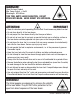
DANGER! Class IIIa Laser Product Max. Power Output: ≤ 5mW Wavelength: 625-645nm THIS TOOL EMITS LASER RADIATION. DO NOT STARE INTO BEAM. AVOID DIRECT EYE EXPOSURE. ATTENTION IMPORTANT • Read all instructions prior to operating this laser tool. Do not remove any labels from tool. • Do not stare directly at the laser beam. • Do not project the laser beam directly into the eyes of others.
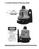
4.
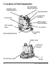
5.
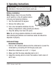
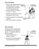
6. Operating Instructions IMPORTANT: It is the responsibility of the user to verify the calibration of the instrument before each use. Battery Installation Note: Always check to be sure that the on/off switch is in the off position before removing and replacing batteries. 1. Turn the instrument 90 degrees. 2. Remove the battery door. 3. Put in four AA alkaline batteries into the battery compartment, noting polarity (as shown). 4. Snap the battery door back into place.
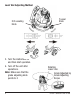
Level Vial Adjusting Method X/Z-Leveling Knob 5. Turn the instrument on and then start operation. 6. Turn off the unit after operations.
Vertical Instruction 1. Put four “AA” alkaline batteries Rotating Z-Direction into the instrument or power Laser Line Leveling Knob the instrument by connecting DC 6V through power jack. 2. Put the instrument on platform or a 5/8" –11 tripod. 3. Adjust the leveling-knob to center the bubble of vial in Z axis. 4. Turn the instrument on and then start 90º Split Laser operation. Beam 5. Turn off the unit after operations.
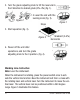
3. Turn the grade adjusting knob to tilt the level vial in the Y-direction to desired grade (0%~4%) (fig. 1). Figure 2 4. Level the vial with the leveling knob (fig. 2). Figure 1 Slope 5. Start operation (fig. 3). Figure 3 Gradient (0-4%) Horizontal 6. Power off the unit after operations, and turn the grade adjusting knob to the 0 position. (fig. 4). Figure 4 Marking Line Instruction Note: Level the instrument.
Turn the instrument to move the vertical laser to a different position Horizontal Laser Line Vertical Laser Line Figure 5 7. Using the Product Operating Panel 1. Power/Vertical Line Button 2. Scan Mode Button 3. Rotation Speed Down Key/Clockwise 4. Rotation Speed Up Key/Counterclockwise 5. Power Light 6. Scan Mode Indicator Light Power On/Off • Power On: With the first press of the power button, the rotating laser and plumb-beam are turned on. Power indicator light is also turned on.
1st Press 2nd Press 3rd Press Power/Vertical Line On Power ON Power Off Press Again • Vertical Line On: With a second press of the power button, the vertical laser is also turned on. • Power Off: A third press of the power button, turns all of the lasers and power indicator lamps off. Rotation / Scan Mode • High Speed Rotation: When turned on, the instrument is in the high-speed rotation mode. This is indicated by the range scan indicator light (continuously on), and rotating laser in high speed.
Up/Down Key • In high-speed rotation mode, pressing the key will increase the rotation speed. Pressing the key will decrease the rotation speed. Note: The instrument rotates in highest speed when it is initially powered on. • In scan mode, pressing the key shifts the scan counterclockwise. Pressing the key shifts the scan clockwise. Remote Control Usage (included in Model No. 40-6505 & 40-6510) Operating Panel 1. Rotation speed up/counter-clockwise 2. Scan button 3 2 3. Rotation speed down/clockwise 4.
Scan Button • Pushing the scan button once will change the laser from full rotation to a small scan. The scan mode indicator light will flash on the laser. • Pushing the scan mode button again will change the laser into its large range scan. • Pushing the scan button a third time will change the laser beam to a dot. • Pushing the scan button a fourth time will change the laser back to its full rotation mode. The scan mode indicator light on the laser will remain constant.
(b) Display 1. Power symbol 2. Low battery symbol 3. Coarse/Fine detection symbol 4. Horn symbol 5. Detecting position symbol 3. Operation Guide (a) Installation of battery • Open the battery-box cap and connect the cords inside with the two polarities of the 9V battery. Note: Take the battery out if the instrument if not used for a long time. • Put the 9V battery into the battery box and close the battery-box cap. (b) Turn on/off • Press the on/off button.
(c) Using the clamp holder 1. grade rod clamp bolt 2. detector connection screw • Attach the detector on the clamp holder by the detector connection screw. • Attach the grade rod clamp to the grade rod or other types of surveying rods by tightening the clamp bolt on the grade rod clamp holder. (d) Detection 1. Coarse detection • Aim the receiving window at the rotating laser instrument.
2. Fine detection 1. power symbol 2. fine detection symbol Figure 6 • Press coarse/fine detection button. The detector is now in fine detection. • Move the instrument up and down like the coarse detection procedure. (e) Horn • Press the horn button. The sound symbol is displayed and the horn is ready for the sound function. The detector then conducts coarse/fine detection through sound (beep) signals. • When the horn signal is a fast beep, move the detector up.
• Avoid knocking the unit over or allowing it to fall on the ground. • Although the instrument is rain resistant, you should avoid submerging the unit in water or other liquids. If unit comes into contact with water or other liquids, wipe it dry immediately. • Do not use unit around fire or expose it to fire in any way. 8. Self-Check IMPORTANT: It is the responsibility of the user to verify the calibration of the instrument before each use. Level Vial Self-Check A. X/Y-Direction Level Vial Self-Check 1.
2. Put the instrument in the vertical position on the tripod. 3. Face the instrument towards wall A, and adjust the leveling knob to center the bubble of Z-direction vial. Project laser beam and mark e2 for the laser point shown on wall A. 4. Measure the distance between e1 and e2. 5. Turn the instrument 180° to face wall B, and turn the adjusting knob and mark the laser point projected on wall B f2. 6. The distance between e1 and e2 should equal the distance between f1 and f2.
3. Measure the distance between a1 and a2, and between b1 and b2. If the distance between a1 and a2 + b1 and b2 is greater than 1/8” at 50 ft.,the accuracy is beyond tolerance, reference section 12 of this document. 9.
10.
11. Care and Handling • This laser unit is a precision tool that must be handled with care. exposing unit to shock vibrations and extreme temperatures. • Before moving or transporting the unit, make sure that the unit is turned off. • Remove the batteries when storing the unit for an extended time (more than three months) to avoid damage to the unit should the batteries deteriorate. • Always store the unit in its case when not in use. • Avoid getting the unit wet.
NOTE: The user is responsible for the proper use and care of the product. It is the responsibility of the user to verify the calibration of the instrument before each use. For further assistance, or if you experience problems with this product that are not addressed in this instruction manual, please contact our Customer Service Department. In the U.S., contact Johnson Level & Tool’s Customer Service Department at 800-563-8553.
14. Accessories AccuLine Pro™ accessories are available for purchase through authorized AccuLine Pro dealers. Use of non-AccuLine Pro accessories will void any applicable limited warranty and there will be NO WARRANTY. If you need any assistance in locating any accessories, please contact our Customer Service Department. In the U.S., contact Johnson Level & Tool’s Customer Service Department at 800-563-8553. In Canada, contact Johnson Level & Tool’s Customer Service Department at 800-346-6682.