
Actuator Install Instructions
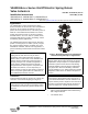
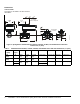
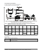


Table Of Contents

VA9208-Bxx-x Series On/Off Electric Spring Return Valve Actuators Installation Instructions 5
5. Install linkage base on Side B using the two
#10-14 x 2.75 in. long screws (Figure 7). The
recommended torque is 20 to 24 lb·in.
(2.3 to 2.7 N·m).
6. Insert fixed pointer and M4x0.7x83 mm long screw
into the Side A actuator hub. Direct the arrow on
the pointer to 100% (Figure 8).
7. Install the actuator on the ball valve (Figure 9).
Tighten the actuator mounting screw to a torque of
10 to 12 lb·in. (1.1 to 1.4 N·m) and snap the large
adjustable pointer into place.
Mounting the Actuator to Spring Return Port A
(Coil) Closed
To mount the actuator to spring return port A (coil)
closed:
1. Turn the valve stem to the position outlined in
Figure 10.
2. Mount optional M9000-561 Thermal Barrier to the
valve if fluid temperature exceeds 212°F (100°C).
See the Mounting the Thermal Barrier
section for
more information.
Note: Proceed to Step 7 if the ball valve linkage is on
actuator Side A.
Figure 7: Installing the Linkage
Figure 8: Installing the Fixed
Pointer
F
I
G
:
F
X
P
T
_
A
Figure 9: Mount the Actuator
F
I
G
:
M
N
T
_
A
C
T
A
Figure 10: Positioning the Valve Stem
F
I
G
:
V
G
1
0
0
0
s
d
B
2 Way
3 Way