
Actuator Install Instructions
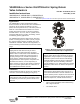
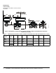
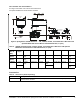


Table Of Contents

VA9208-Bxx-x Series On/Off Electric Spring Return Valve Actuators Installation Instructions4
Mounting
Mounting the Actuator to Spring Return Port A
(Coil) Open
To mount the actuator to Spring Return Port A (Coil)
open:
1. Turn the valve stem to the position outlined in
Figure 4.
2. Mount optional M9000-561 Thermal Barrier to the
valve if fluid temperature exceeds 212°F (100°C).
See the Mounting the Thermal Barrier
section for
more information.
Note: Proceed to Step 7 if the ball valve linkage is on
actuator Side B.
3. Remove the linkage from Side A (Figure 5).
4. Insert the drive shaft into Side B (Figure 6).
M9000-560 Ball Valve Linkage Kit for applying M9203 and M9208 Series Actuators to VG1000 Series Valves
(Quantity 1)
M9000-561 Thermal Barrier Extends M(VA)9104, M(VA)9203, and M(VA)9208 Series Electric Spring Return Actuator
Applications to Include Low Pressure Steam (Quantity 1)
M9000-341 Weathershield Kit for VG1000 Series Ball Valve application of M(VA)9104, M(VA)9203, and M(VA)9208
Series Electric Spring Return Actuators (Quantity 1)
M9208-604 Replacement Manual Override Cranks with Long Crank Radius: 2.83 in. (72 mm) (Quantity 5)
M9208-605 Replacement Manual Override Cranks with Short Crank Radius: 1.83 in. (46.5 mm) (Quantity 5)
Table 3: Accessories (Order Separately) (Continued)
Code Number Description
Figure 4: Positioning the Valve Stem
F
I
G
:
V
G
1
0
0
0
3 Way2 Way
Figure 5: Removing the Linkage
F
I
G
:
R
M
V
_
L
N
K
Figure 6: Inserting the Drive Shaft
F
I
G
:
D
R
V
_
S
H
F
T
_
B