
Actuator Install Instructions
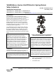
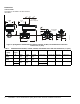
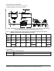
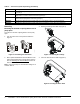
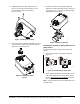
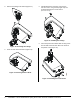
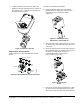

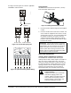
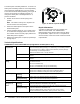
Table Of Contents

VA9208-Bxx-x Series On/Off Electric Spring Return Valve Actuators Installation Instructions10
The switch point of Auxiliary Switch No. 1 is fixed. The
switch point of Auxiliary Switch No. 2 is independently
and continuously adjustable from 74 to 5% position.
For the most accurate switch positioning, see Figure 22
and use the method in the following example. To
change the switch point of Auxiliary Switch No. 2,
proceed as follows:
1. Position the actuator in the full spring return
position.
Note: The switch is factory set to trip when the
actuator reaches the 10% position.
2. Rotate the switch adjuster until it points to the
desired switch point.
3. Connect Auxiliary Switch No. 2 to a power source
or an ohmmeter and apply power to the actuator.
The actuator moves to the fully open position and
holds while power is applied.
4. Observe the switch point. If required, repeat Step 1
through Step 3.
Repair Information
A number of replacement parts are available; see
Table 3 for more details. If an VA9208 Series
Electric Spring Return Actuator fails to operate within
its specifications, replace the unit. For a replacement
electric actuator, contact the nearest Johnson Controls
representative.
Technical Specifications
Figure 22: Switch Trip Point Settings
F
I
G
:
S
W
_
T
R
P
VA9208-Bxx-x Series On/Off Electric Spring Return Actuator (Part 1 of 2)
Power
Requirements
-BGx Models AC 24 V (AC 18 V to 30 V) at 50/60 Hz: Class 2 (North America) or Safety
Extra-Low Voltage (SELV) (Europe), 6.1 VA Running, 1.2 VA Holding Position
DC 24 V (DC 21.6 V to 28.8 V): Class 2 (North America) or SELV (Europe)
3.5 W Running, 0.5 W Holding Position
Minimum Transformer Size: 7 VA per Actuator
-BAx Models AC 120 V (AC 102 V to 132 V) at 60 Hz: 0.05 A Running, 0.03 A Holding
Position
-BDx Models AC 230 V (AC 198 V to 264 V) at 50/60 Hz: 0.04 A Running, 0.03 A Holding
Position
Auxiliary Switch
Rating
-xxC Models Two Single-Pole, Double-Throw (SPDT), Double-Insulated Switches with Gold
over Silver Contacts:
AC 24 V, 50 VA Pilot Duty
AC 120 V, 5.8 A Resistive, 1/4 hp, 275 VA Pilot Duty
AC 240 V, 5.0 A Resistive, 1/4 hp, 275 VA Pilot Duty
Spring Return Direction is Selectable with Mounting Position of Actuator:
Actuator Face Labeled A is Away from Valve: CCW Spring Return
Actuator Face Labeled B is Away from Valve: CW Spring Return
Rated Torque Power On
(Running)
70 lb·in. (8 N·m) All Operating Temperatures
Power Off
(Spring Returning)
70 lb·in. (8 N·m) at Standard Operating Temperatures
53 lb·in. (6 N·m) at Extended Operating Temperatures
Rotation Range Maximum Full Stroke: 95°
Rotation Time for
90 Degrees of
Travel
Power On
(Running)
55 to 71 Seconds for 0 to 70 lb·in. (8 N·m) Load, at all Operating Conditions
60 Seconds Nominal at Full Rated Load (0.25 rpm)
Power Off
(Spring Returning)
13 to 26 Seconds for 0 to 70 lb·in. (8 N·m) Load, at Room Temperature
21 Seconds Nominal at Full Rated Load
39 Seconds Maximum with 70 lb·in. (8 N·m) Load, at -4°F (-20°C)
108 Seconds Maximum with 53 lb·in. (6 N·m) Load at -40°F (-40°C)