
Actuator Install Instructions

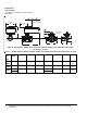
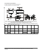


Table Of Contents

VA9208-AGx-x Series On/Off and Floating Point Electric Spring Return Valve Actuators Installation
Instructions
5
4. Insert the drive shaft into Side B (Figure 6).
5. Install linkage base on Side B using the two
#10-14 x 2.75 in. long screws (Figure 7). The
recommended torque is 20 to 24 lb·in.
(2.3 to 2.7 N·m).
6. Insert fixed pointer and M4x0.7x83 mm long screw
into the Side A actuator hub. Direct the arrow on
the pointer to 100%.
7. Install the actuator on the ball valve (Figure 9).
Tighten the actuator mounting screw to a torque of
10 to 12 lb·in. (1.1 to 1.4 N·m) and snap in the large
adjustable pointer into place.
Figure 6: Inserting the Drive Shaft
F
I
G
:
D
R
V
_
S
H
F
T
_
B
Figure 7: Installing the Linkage
Figure 8: Installing the Fixed Pointer
F
I
G
:
F
X
P
T
_
A
Figure 9: Mount the Actuator
F
I
G
:
M
N
T
_
A
C
T
A