
Install Instructions
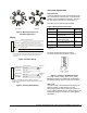
Table Of Contents

VA-4233-GGx Series Electric Valve Actuators Installation Instructions 5
Calibration
During normal operation, if the actuator stroke
increases in the auto mode due to seal or seat wear,
the input is redefined to the increased rotation range in
approximately 2° increments.
AUTO Stroke Calibration
Initial application of a power signal will drive the
actuator and valve assembly to the full stem-up
position and then the full stem-down position, and will
store these positions in nonvolatile memory (retains
data when power is lost or removed). The actuator will
then drive to the midpoint, and then to the position
determined by the applied control signal.
If the valve stroke increases due to disk or seat wear
during normal operation, the actuator automatically
calibrates to the increased stroke range. While AUTO
stroke calibrating, the valve control function could be
lost for up to three minutes. If this temporary loss of
control function will result in system control problems
during startup, the actuator should be mounted to the
valve and have electric power supplied to it prior to
startup. Doing so will allow the actuator to AUTO
stroke calibrate itself. The Johnson Controls
M9000-200 Commissioning Tool (ordered separately)
is a convenient method for applying power to the
actuator prior to startup.
Canceling the Stored Memory
The actuator will AUTO stroke calibrate only once,
upon initial power application. Certain conditions, such
as removal of the actuator from the valve, require
cancellation of the stored memory for the actuator to
adjust to its new position once it is remounted on the
valve. To cancel the stored memory of an actuator that
has been removed from the valve, proceed as follows:
1. Apply power to the actuator.
2. Open the door on the top of the actuator and move
the Fixed/Auto switch to the Fixed position for ten
seconds. Doing so will cancel the stored memory.
3. Remove power from the actuator.
4. Move the Fixed/Auto switch back to the Auto
position.
Checkout
To confirm that the auxiliary switches are set at the
desired switch points, proceed as follows:
1. Disconnect the actuator from the system
controller.
2. Apply an external power supply and a DC input
signal, and check the upper and lower switch point
settings. The Johnson Controls M9000-200
Commissioning Tool (ordered separately) is a
convenient method for applying power to the
actuator.
If the upper and lower settings are set at the
desired switch points, proceed to Step 3; if not,
repeat the auxiliary switch adjustment steps until
the desired switch point settings are obtained.
3. Remove the M9000-200 Commissioning Tool
(if used) and reconnect the actuator to the system
controller.