
Install Instructions
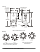
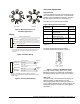
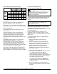
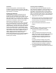
Table Of Contents

4 VA-4233-GGx Series Electric Valve Actuators Installation Instructions
Table 2: Available Input Control Signals
Mode
Switch 5
Mode
Switch 4
Mode
Switch 1
Control Signal
VDC mA 0-10 2-10 — 6-9
0-10
XXX
2-10
XXX
Voltage
Input
(VDC)
6-9
XX X
0-20
XX X
Current
Input
(mA)
4-20
XXX
Input Signal
The range of the input signal is determined by the
position of Switches 1 and 4. (See Table 1.)
With Switch 5 in the mA position, the feedback signal
varies within the 0 to 10 V, 2 to 10 V, or 6 to 9 V range.
Fixed or Auto Mode
The actuators are factory set with Switch 2 in the
AUTO position.
The AUTO calibration or auto mode enables the
actuator to redefine the selected input signal and
feedback proportionally across a reduced rotation
range. The actuator stores the reduced range in
nonvolatile memory (retains data when power is lost or
removed).
The FIXED position is where a 0 to 10 VDC input
signal (selected with Switches 1, 4, and 5)
corresponds with a 0 to 93° rotation. If the rotation
range is reduced, the end-stop is reached with a
reduced input signal. For example, if a 0 to 10 VDC
input signal is selected and the rotation range is limited
to 75°, the end-stop is reached at 8 VDC.
If the actuator’s mounting position is changed or the
linkage adjusted, reinitiate the auto mode by moving
Switch 2 to fixed for 5 seconds and then back to auto.
Auxiliary Switch Adjustments
(VA-4233-GGC-2 and -2MP Only)
!
WARNING: Electrical Shock Hazard.
Be sure that all unused auxiliary switch leads are
insulated to avoid the risk of electric shock or
damage to the equipment.
The VA-4233-GGC-2 and -2MP Electric Valve
Actuators feature two integral auxiliary switches with
switch adjusters accessible on either face of the
actuator.
IMPORTANT: Do not force the switch adjuster
out of the allowable range, or damage to the
auxiliary switch may occur.
Switch points are independently and continuously
adjustable from approximately 0 to 74% of maximum
actuator travel for Auxiliary Switch 1, and
approximately 22 to 100% of maximum actuator travel
for Auxiliary Switch 2.
If only one auxiliary switch is needed, use the
appropriate switch. Use Auxiliary Switch 1 for the
upper switch point, and Auxiliary Switch 2 for the lower
switch point.
To change the switch points to the desired setting,
proceed as follows:
1. Disconnect the actuator from the system
controller.
2. Use the manual hand crank (included with the
actuator) or an external power supply and a
DC input signal to position the valve stem to the
desired switch point. The Johnson Controls
M9000-200 Commissioning Tool (ordered
separately) is a convenient method for applying
power to the actuator.
3. Use a 1/8 in. (3 mm) blade screwdriver to turn the
auxiliary switch until it just trips.
2. Looking at the actuator face with the
engraved markings, clockwise rotation of the
switch adjuster lowers the stem setting toward the
valve, while counterclockwise rotation raises the
stem setting away from the valve.
3. Looking at the actuator face without the
engraved markings, the switch adjuster rotation
would be reversed.
4. Remove the M9000-200 Commissioning Tool
(if used) and reconnect the actuator to the system
controller.