
Install Instructions
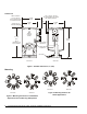
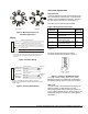
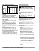
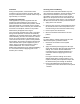
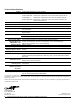
Table Of Contents

VA-4233-GGx Series Electric Valve Actuators Installation Instructions 3
Face View Side View
Figure 4: Mounting Positions for
Hot Water Applications
Wiring
Gray
White/Red
Ye l l ow
White
Red
Output 20 VDC at 25 mA*
Feedback 0 (2) to 10 VDC or 6 to 9 VDC
Input 0 (2) to 10 VDC, 6 to 9 VDC, or 0 (4) to 20 mA**
24 VAC/VDC
Common
** The control inputs shown will move the valve stem down as
the control input increases, with the DA/RA switch in the
DA mode.
* Available on VA-4233-GGx-2MP models only.
Figure 5: Actuator Wiring
White/Yellow
Black/Yellow
Switch S1
21%*
White/Gray
White/Blue
Switch S2
84%*
Black/Gray
Black/Blue
* Refers to a full actuator stroke of 29/32 in. (23 mm).
Switches are readjustable to all applicable Johnson Controls
stroke ranges.
N.C. (26)
Common (24)
N.O. (25)
Common (21)
N.O. (23)
N.C. (22)
Figure 6: Auxiliary Switch Wiring
Setup and Adjustments
Mode Switches
The mode selection switches are located behind the
door on the bottom of the actuator. To access these
switches, insert a flat-blade screwdriver in the slot at
the door edge to open the door. (See Figure 1.)
See Table 1for the mode settings available.
Table 1: Mode Selection Information
Mode
Switches
Switch Functions Factory
Settings
5
VDC or mA VDC
4
0-10 VDC (0-20 mA) or 2-10
VDC (4-20 mA)
0-10
3
Direct Acting (DA) or
Reverse Acting (RA)
DA
2
Fixed or Auto (See the Fixed
or Auto Mode section.)
Auto
1
— or 6-9 VDC —
Note: The 6 to 9 VDC setting of Switch 1 overrides
Switch 4.
The mode switches are factory set with all
five switches positioned as shown in Figure 7:
mA
2-10
RA
AUTO
6-9
VDC
0-10
DA
FIXED
5
4
3
2
1
Figure 7: Position of the Mode Switches
To change a factory setting, use a 1/8 in. (3 mm)
flat-blade screwdriver to position the mode switch to
the alternate setting. Close the door when finished.
VDC or mA
The type of input control signal is determined by the
position of Switch 5. When Switch 5 is in the
VDC position (factory setting), the input signal is set
for DC voltage. When Switch 5 in the mA position, the
input signal changes to current input. (See Figure 7
and Table 2.)