
Install Instructions
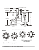
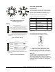
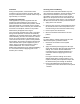
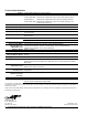
Table Of Contents

2 VA-4233-GGx Series Electric Valve Actuators Installation Instructions
Dimensions
Allow a minimum
1-1/2 in. (38 mm)
top and side clearance
for actuator removal.
6-11/32
(161)
Top of
Valve Bonnet to
Top of Actuator
Face Vie
w
Side Vie
w
11/32
(9)
Set Screw
4-3/32
(104)*
3-5/32
(80)
3-19/32
(91)
* Add 1-17/32 in. (39 mm)
for conduit adaptor on models
with auxiliary switches.
Stem Nut
Connector
Area
Auxiliary Switch 2
Adjustment
Auxiliary Switch 1
Adjustment
Access Door to
Actuator Settings
6-13/16
(173)
Manual
Override
Socket
Figure 1: Actuator Dimensions, in. (mm)
Mounting
Face View Side View
Figure 2: Mounting Positions for Chilled Water
Applications and Condensing Atmospheres
Face View Side View
Figure 3: Mounting Positions for
Steam Applications