
Install Instructions
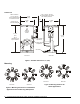
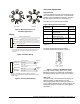
Table Of Contents

Installation Instructions
Issue Date August 11, 2003
© 2003 Johnson Controls, Inc. 1
Part No. 34-1280-114, Rev. B www.johnsoncontrols.com
VA-4233-GGx Series
Electric Valve Actuators
Installation
Refer to Figures 2 through 4 for proper actuator
orientation before attempting to make the installation.
IMPORTANT: Use this VA-4233-GGx Series
Electric Valve Actuator only to control equipment
under normal operating conditions. Where failure or
malfunction of the VA-4233-GGx Actuator could lead
to personal injury or property damage to the
controlled equipment or other property, additional
precautions must be designed into the control
system. Incorporate and maintain other devices such
as supervisory or alarm systems or safety or limit
controls intended to warn of, or protect against,
failure or malfunction of the VA-4233-GGx Actuator.
VA-4233-GGx Series Proportional Electric Valve
Actuators operate on 24 VAC at 50/60 Hz or 24 VDC,
and use a stepper motor with stall detection circuitry
that operates throughout the entire actuator stroke. All
models employ noise-filtering techniques on the
control signal to eliminate repositioning due to line
noise.
VA-4233-GGx Series Actuators position the valve
in response to a control signal, in a manner defined
by the mode switch that is field selected: 0 to 10,
2 to 10, or 6 to 9 VDC, or 0 to 20 or 4 to 20 mA input
signal. A built-in direct or reverse (DA/RA) switch
allows selection of the required control action. These
actuators feature an AUTO stroke calibration function
that enables the actuator to scale the selected input
signal and feedback proportionally across the actual
valve stroke.
To install the actuator onto the valve, proceed as
follows:
1. Open the door on the top of the actuator and
check that the Fixed/Auto switch is in the Auto
position. Also check that the Control Signal mode
switches are set to the desired input range.
2. Depress the socket for the manual override to be
certain that the actuator is in the retracted position.
3. Using the manual hand crank (included with the
actuator), push in and turn the crank in the
direction of the arrow approximately four full turns.
Lock this position by winding the manual hand
crank counterclockwise to the Lock Area zone
(engraved on the face of the actuator). Remove
the manual hand crank.
4. If replacing a Johnson Controls® M100, V-400,
V-500, or MP8000 Series Actuator on a
VG7000 Series Bronze Control Valve, thread a
VG7000-1016 Bonnet Adaptor (ordered
separately) onto the valve. Then proceed to
Step 5.
1. If installing the VA-4233-GGx Series Actuator
on a 1/2 through 1-1/4 in. Invensys VB-7xxx or
VB-9xxx Series Valve, use the parts included in
the V-9999-BC1 Mounting Kit (ordered
separately). Refer to the literature included with
this kit, V-9999-BC1 Mounting Kit to Mount
VA-715x or VA-720x Series Electric Actuators to
Barber-Colman
1/2 through 1-1/4 inch VB-9xxx
Valve Bodies (Part No. 14-1116-3), to complete
the actuator installation.
5. Thread the jam nut (included with the actuator)
onto the valve stem to the bottom of the threads.
Then thread the special stem nut (included with
the actuator) onto the valve stem, with the beveled
side up. Position the stem nut so that half of a
thread of the valve stem is exposed above the
stem nut.
6. Using two adjustable wrenches, tighten the jam
nut into the stem nut to secure the assembly in
place.
7. Install the actuator and yoke assembly onto the
stem nut assembly, making sure that the flats of
the special stem nut are aligned with the internal
flats of the actuator stem nut connector. When
properly installed, the actuator will be aligned with
the valve body.
8. Tighten the set screw to a torque of 10 to 20 lb·in
(1.1 to 2.3 N·m), to secure the assembly.