
User Guide
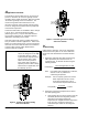
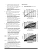


Table Of Contents
- Features and Benefits
- Application Overview
- Valve Sizing
- V46 Flowcharts
- Dimensions
- Table 1: Commercial Service V46 Threaded Connection Dimensions
- Table 2: Commercial Service: V46 Flange Connection Dimensions
- Table 3: Maritime Service: ASME Flange Connection Dimensions
- Table 4: Navy “BuShips” Service: Navy Flange Connection Dimensions
- Mounting Adjustment
- Table 5: Range Adjustment Screw
- Manual Flushing
- Companion Flanges and Gaskets
- Repair Data
- Ordering Information
- Table 6: Companion Flange Kits
- Product Number Selection
- Table 7: Type Number Selection Matrix Table 8: Pressure Connection Styles
- Options
- Capillary Tubing Length
- Mounting Bracket
- Table 9: Direct- Acting Commercial Type - Non- corrosive Refrigerants
- Table 10: Commercial Type - Ammonia
- Table 11: Reverse Acting Commercial Type - Non- corrosive Refrigerants
- Table 12: Maritime Type - Non- corrosive Refrigerants
- Table 13: Navy Type - Non- corrosive Refrigerants
- Table 14: Pressure Range Specifications
- Specifications

8 V46 Series Pressure-Actuated Water-Regulating Valves Product/Technical Bulletin
M
anual Flushing
To clear any sediment that might accumulate, valves
may be manually flushed. Insert screwdrivers under
both sides of the valve spring guide and lift upwards to
flush the valve. See Figure 6. Manual flushing does
not affect valve adjustment.
Valve Spring
Guide
Top
Retainer
Range
Spring
Insert screwdrivers
underneath the valve
spring guide.
Figure 6: Manual Flushing
R
epair Data
Replacement of the sensing element, internal parts,
and the rubber diaphragm can be made. For a
replacement valve or replacement parts kit, contact the
nearest Johnson Controls/PENN distributor. For
replacement part kit numbers, refer to Tables 9
through 13. For replacement kit instructions and
details refer to the following bulletins:
V46, V47, V48,
and V49 Sensing Element Replacement
and
V46, V47,
246, and 247 Repair Parts and Service Instructions.
O
rdering Information
When ordering water valves, specify the following:
1. Complete product number.
2. If product number is not known, answer the
following questions and select a valve using
Tables 9 through 13.
a. What is the valve size needed? See
Valve
Sizing
section.
b. What refrigerant will be used in the system?
See
Table 14: Pressure Range Specifications
.
Note: 3/8 in. through 1-1/2 in. valves are
supplied with all range construction,
allowing a single valve to be used for
either low or high range refrigerants.
c. Is a standard open high, or reverse action
close high valve required? See
Table 7: Type
Number Selection Matrix.
d. Is a commercial, maritime, or Navy service
valve needed? Maritime and Navy valves
have bronze bodies and monel internal parts.
3. Companion flange kit by part number, if required.
See section below and
Table 6: Companion
Flange Kits
.
4. Mounting bracket (3/8 in. and 1/2 in. valve sizes
only) if required, and its position on valve. See
Table 8: Pressure Connection Styles
.
Companion Flanges and Gaskets
Kits are available, at additional cost, for 1-1/2, 2, and
2-1/2 in. flange connection (ASME specifications)
valves only. Each flange kit contains two ring gaskets,
two cast iron flanges, eight machine bolts, and eight
hex nuts.
Hex Nut (8)
Machine
Bolt (8)
Cast Iron
Flange (2)
Ring Gasket for
1-1/2, 2, and
2-1/2 in. Kits (2)
Figure 7: Flange Kit
Table 6: Companion Flange Kits
Kit Number Water Valve Size
KIT 14A-612
1-1/2 in.
KIT 14A-613
2 in.
KIT 14A-614
2-1/2 in.
Product Number Selection
For applications that call for valves not listed in
Tables 9 through 13,
Table 7:
Type Number Selection
Matrix
can be used to specify a custom valve.
Example: To order a direct-acting, commercial valve
with a 1-1/4 in. NPT threaded connection,
specify a V46AE.