
User Guide
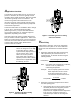
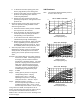


Table Of Contents
- Features and Benefits
- Application Overview
- Valve Sizing
- V46 Flowcharts
- Dimensions
- Table 1: Commercial Service V46 Threaded Connection Dimensions
- Table 2: Commercial Service: V46 Flange Connection Dimensions
- Table 3: Maritime Service: ASME Flange Connection Dimensions
- Table 4: Navy “BuShips” Service: Navy Flange Connection Dimensions
- Mounting Adjustment
- Table 5: Range Adjustment Screw
- Manual Flushing
- Companion Flanges and Gaskets
- Repair Data
- Ordering Information
- Table 6: Companion Flange Kits
- Product Number Selection
- Table 7: Type Number Selection Matrix Table 8: Pressure Connection Styles
- Options
- Capillary Tubing Length
- Mounting Bracket
- Table 9: Direct- Acting Commercial Type - Non- corrosive Refrigerants
- Table 10: Commercial Type - Ammonia
- Table 11: Reverse Acting Commercial Type - Non- corrosive Refrigerants
- Table 12: Maritime Type - Non- corrosive Refrigerants
- Table 13: Navy Type - Non- corrosive Refrigerants
- Table 14: Pressure Range Specifications
- Specifications

V46 Series Pressure-Actuated Water-Regulating Valves Product/Technical Bulletin 7
Table 4: Navy “BuShips” Service: Navy Flange Connection Dimensions
Dimensions in Inches
Valve SizeABCDEFGH I
3/4 in. 4-3/16 7-3/4 4 7/16 3-13/16 1-1/8 2-1/32 1/2 3-5/16
1 in 5-5/16 9 4-1/2 1/2 4-1/4 1-1/4 2-5/8 1/2 4
1-1/4 in. 5-5/16 9-11/32 4-11/16 1/2 4-1/2 1-5/8 2-5/8 1/2 4-5/32
1-1/2 in. 5-5/16 10-7/32 5-3/4 1/2 5-1/16 1-7/8 2-5/8 1/2 4
2 in. 6-3/8 14-1/8 6-13/32 1/2 5-9/16 2-3/4 3-1/2 7/16 7-9/32
2-1/2 in. 6-3/8 14-5/16 6-1/2 1/2 6-1/8 2-3/4 3-1/2 5/8 7-3/16
Navy Flange Specifications
Valve Size No. of Holes Hole Size Bolt Circle
3/4 in. 4 9/16 2-11/16
1 in 4 9/16 3-1/8
1-1/4 in. 4 9/16 3-3/8
1-1/2 in. 6 9/16 3-15/16
2 in. 6 9/16 4-7/16
2-1/2 in. 6 9/16 5
M
ounting
!
CAUTION: Equipment Damage Hazard.
To prevent damage to the
capillary, avoid sharp bends or
kinks in the capillary. Coil and
secure excess capillary at the
valve end to avoid tube breakage
due to vibration. Because
harmonic vibration can also break
the tube, some slack must be left
in the capillary. Do not permit the
tubing to rub against metal
surfaces where friction can
damage the capillary.
Flush water lines to clear any foreign matter that may
interfere with valve operation. Mount valves vertically
on the inlet side of the condenser with spring housing
up. If it is necessary to keep the condenser flooded
with coolant, the valve can be mounted on the outlet
side. When mounting the valve in a position other than
vertical, follow the instructions of the equipment in
which the valve will be installed. Make refrigerant head
pressure connection to bellows. If additional capillary
tubing is required, use 1/4 in. O.D. tubing or larger.
A
djustment
Valves may be adjusted with standard service valve
wrenches or screwdrivers, see Table 5. All range
valve settings can be changed quickly from low-range
refrigerants such as R134 to high-range refrigerants
such as R22 or vice versa. To raise the valve opening
point, turn the adjusting screw, located at the top of
range spring housing, counterclockwise. See Figure 8.
Turn the adjusting screw clockwise to lower the
opening point. Exact settings can be made using a
pressure gauge in the refrigerant line to determine the
throttling point. Put the system under normal operating
load and adjust to the desired operating pressure. See
Table 14 for pressure range specifications.
Table 5: Range Adjustment Screw
Valve Size (in.) Range Adjusting Screw
3/8, 1/2, 3/4 1/4 in. square head adjusting screw with
a screwdriver slot
1, 1-1/4, 1-1/2 5/16 in. square head adjusting screw
2, 2-1/2 1/2 in. square head adjusting screw and
a slotted cam
If the compressor operates in high ambient
temperatures, head pressures may remain high
enough during off cycles to prevent the valve from
closing completely. In such instances, the opening
point of the valve should be raised just enough to
cause the valve to close during compressor standby
periods. This will also raise the throttling point.