
User Guide
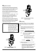
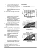


Table Of Contents
- Features and Benefits
- Application Overview
- Valve Sizing
- V46 Flowcharts
- Dimensions
- Table 1: Commercial Service V46 Threaded Connection Dimensions
- Table 2: Commercial Service: V46 Flange Connection Dimensions
- Table 3: Maritime Service: ASME Flange Connection Dimensions
- Table 4: Navy “BuShips” Service: Navy Flange Connection Dimensions
- Mounting Adjustment
- Table 5: Range Adjustment Screw
- Manual Flushing
- Companion Flanges and Gaskets
- Repair Data
- Ordering Information
- Table 6: Companion Flange Kits
- Product Number Selection
- Table 7: Type Number Selection Matrix Table 8: Pressure Connection Styles
- Options
- Capillary Tubing Length
- Mounting Bracket
- Table 9: Direct- Acting Commercial Type - Non- corrosive Refrigerants
- Table 10: Commercial Type - Ammonia
- Table 11: Reverse Acting Commercial Type - Non- corrosive Refrigerants
- Table 12: Maritime Type - Non- corrosive Refrigerants
- Table 13: Navy Type - Non- corrosive Refrigerants
- Table 14: Pressure Range Specifications
- Specifications

V46 Series Pressure-Actuated Water-Regulating Valves Product/Technical Bulletin 3
b. To determine the valve opening point, add
about 7 psig (48 kPa) to the closing point.
c. From the same table, read the operating head
pressure corresponding to the selected
condensing temperature.
d. Subtract the valve opening point from the
operating head pressure. This gives the head
pressure rise.
3. Determine water pressure drop across the valve.
This is the pressure actually available to force
water through the valve.
a. Determine minimum water pressure available
from city mains or other sources.
b. From condensing unit manufacturer’s tables,
read the pressure drop through condenser
corresponding to the required flow.
c. To the value found in 3b, add the estimated or
calculated drop through installed piping.
d. Subtract the total condenser, piping, and static
head (if applicable) pressure drop from the
available water pressure found in 3a. This is
the available pressure drop across the valve.
4. Select the proper valve size from the V46
flowcharts by locating a point on a chart that will
satisfy the flow, the head pressure rise above
opening point, and the pressure drop across the
valve.
Example: The required flow for a low-range system is
found to be 27 GPM. Condensing pressure
is 125 psig, and the maximum ambient
temperature is estimated at 86°F. City water
pressure is 40 psig and the manufacturer’s
table gives a pressure drop through the
condenser and the accompanying piping
and valves at 15 psi. Drop through the
installed piping is approximately 4 psi.
Step 1: 27 GPM
Step 2: Closing point is pressure of refrigerant
corresponding to 86°F = 93 psig
Opening point = 93+7 = 100 psig
Operating head pressure = 125 psig
Head pressure rise = 125-100 = 25 psi
Step 3: Minimum pressure = 40 psig
Pressure drop through condenser = 15 psi
Combined pressure drop = 15+4 = 19 psi
Pressure drop across valve = 40-19 = 21 psi
Using a flow of 27 GPM, a head pressure rise of
25 psi, and a pressure drop across the valve of 21 psi,
the only valve that satisfies all three criteria is a
1-1/4 in. valve. See the 1-1/4 in. V46 - All Range chart
on the next page.
V46 Flowcharts
Note: The maximum differential water pressure
across a valve is 60 psi.
60
30
10
Pressure Drop Across Valve (psi)
3/8 in. V46DA - Low Flow
0
0.5
1
1.5
2
2.5
10 20 30 40 50 60
Head Pressure Rise
Above Opening Point (psi)
Flow (GPM)
60
50
40
30
20
10
5
2
Pressure Drop Across Valve (psi)
3/8 in. V46 - All Range
0
2
4
6
8
10
12
14
16
10 20 30 40 50 60
Head Pressure Rise
Above Opening Point (psi)
Flow (GPM)
60
50
40
30
20
10
5
2
Pressure Drop Across Valve (psi)
1/2 in. V46 - All Range
0
5
10
15
20
25
30
10 20 30 40 50 60
Head Pressure Rise
Above Opening Point (psi)
Flow (GPM)