
User Guide
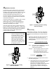
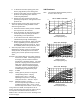


Table Of Contents
- Features and Benefits
- Application Overview
- Valve Sizing
- V46 Flowcharts
- Dimensions
- Table 1: Commercial Service V46 Threaded Connection Dimensions
- Table 2: Commercial Service: V46 Flange Connection Dimensions
- Table 3: Maritime Service: ASME Flange Connection Dimensions
- Table 4: Navy “BuShips” Service: Navy Flange Connection Dimensions
- Mounting Adjustment
- Table 5: Range Adjustment Screw
- Manual Flushing
- Companion Flanges and Gaskets
- Repair Data
- Ordering Information
- Table 6: Companion Flange Kits
- Product Number Selection
- Table 7: Type Number Selection Matrix Table 8: Pressure Connection Styles
- Options
- Capillary Tubing Length
- Mounting Bracket
- Table 9: Direct- Acting Commercial Type - Non- corrosive Refrigerants
- Table 10: Commercial Type - Ammonia
- Table 11: Reverse Acting Commercial Type - Non- corrosive Refrigerants
- Table 12: Maritime Type - Non- corrosive Refrigerants
- Table 13: Navy Type - Non- corrosive Refrigerants
- Table 14: Pressure Range Specifications
- Specifications

2 V46 Series Pressure-Actuated Water-Regulating Valves Product/Technical Bulletin
A
pplication Overview
The V46 direct-acting models open on an increase in
pressure. Models A, B, and C are typically used for
regulating water-cooled condensers, while the low flow
“D” model is generally used in ice machines. The
reverse-acting V46N valve model closes on an
increase in pressure and is typically used for bypass
service on refrigeration systems and heat pumps that
control water temperature.
Commercial V46 valves are available in 3/8 in. through
2-1/2 in. sizes. Commercial all range models
(3/8 through 1-1/2 in.), may be used with standard
non-corrosive refrigerants, or ammonia refrigerant
applications, depending on the model.
V46 series valves also come in models designed for
Navy or maritime salt water applications. These valve
bodies are constructed of bronze, and any metal parts
that come into contact with salt water are constructed
of nickel copper (monel), which withstands the
corrosive action of salt water.
IMPORTANT: All V46 Series water regulating
valves are designed for use only
as operating devices. Where
system closure, improper flow, or
loss of pressure due to valve
failure can result in personal
injury and/or loss of property, a
separate pressure relief or safety
shutoff valve, as applicable, must
be added by the user.
INLET
Figure 2: Threaded Type Direct-Acting
Valve Cross Section
INLET
Figure 3: Threaded Type Reverse-Acting
Valve Cross Section
V
alve Sizing
Follow Steps 1 through 3, and use the information
obtained to locate a point on one of the flowcharts
found under
V46 Flowcharts
that satisfies all three
steps.
1. Determine maximum water flow required using
tables provided by the manufacturer of the
condensing unit, or calculate the flow using the
following formula:
Flow (GPM)
Tons of Refrigeration x15,000
500 x (Outlet -Inlet Temperature)
=
Note: If the outlet water temperature is unknown,
assume it to be 10
°
F below the
condensing temperature.
Example: A 9 ton capacity system has an inlet
water temperature of 65
°
F and an
outlet water temperature of 95
°
F.
The maximum required water flow is:
Flow (GPM)
9 x15,000
500 x (95 - 65)
9GPM
==
2. Determine refrigerant head pressure rise above
the valve opening point.
a. Valve closing point (to assure closure under all
conditions) must be the refrigerant pressure
equivalent to the highest ambient air
temperature the equipment will be subjected to
in the off cycle. Read this in psig from a
“Saturated Vapor Table” for the refrigerant
selected.