
User Guide


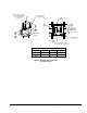
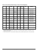

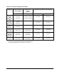


Table Of Contents
- Features and Benefits
- Application Overview
- Valve Sizing
- V46 Flowcharts
- Dimensions
- Table 1: Commercial Service V46 Threaded Connection Dimensions
- Table 2: Commercial Service: V46 Flange Connection Dimensions
- Table 3: Maritime Service: ASME Flange Connection Dimensions
- Table 4: Navy “BuShips” Service: Navy Flange Connection Dimensions
- Mounting Adjustment
- Table 5: Range Adjustment Screw
- Manual Flushing
- Companion Flanges and Gaskets
- Repair Data
- Ordering Information
- Table 6: Companion Flange Kits
- Product Number Selection
- Table 7: Type Number Selection Matrix Table 8: Pressure Connection Styles
- Options
- Capillary Tubing Length
- Mounting Bracket
- Table 9: Direct- Acting Commercial Type - Non- corrosive Refrigerants
- Table 10: Commercial Type - Ammonia
- Table 11: Reverse Acting Commercial Type - Non- corrosive Refrigerants
- Table 12: Maritime Type - Non- corrosive Refrigerants
- Table 13: Navy Type - Non- corrosive Refrigerants
- Table 14: Pressure Range Specifications
- Specifications

V46 Series Pressure-Actuated Water-Regulating Valves Product/Technical Bulletin 11
HIGHER
INLET
2
3
4
1
Four mounting bracket
positions (1-4) are available.
9/32 Diameter
Holes (2)
Bracket Shown
in Position (1)
B
A
C
Range Adjusting
Screw
Dimensions: in. (mm)
Valve Size A B C
3/8
2 (51) 1.25 (32) 1.38 (35)
1/2
2 (52) 1.85 (47) 1.52 (39)
Range Adjusting Screw
(Turn counterclockwise
to raise operation
setpoint.)
Figure 8: Mounting Bracket for 3/8 in.
and 1/2 in. Valves