
User Guide
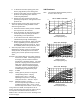


Table Of Contents
- Features and Benefits
- Application Overview
- Valve Sizing
- V46 Flowcharts
- Dimensions
- Table 1: Commercial Service V46 Threaded Connection Dimensions
- Table 2: Commercial Service: V46 Flange Connection Dimensions
- Table 3: Maritime Service: ASME Flange Connection Dimensions
- Table 4: Navy “BuShips” Service: Navy Flange Connection Dimensions
- Mounting Adjustment
- Table 5: Range Adjustment Screw
- Manual Flushing
- Companion Flanges and Gaskets
- Repair Data
- Ordering Information
- Table 6: Companion Flange Kits
- Product Number Selection
- Table 7: Type Number Selection Matrix Table 8: Pressure Connection Styles
- Options
- Capillary Tubing Length
- Mounting Bracket
- Table 9: Direct- Acting Commercial Type - Non- corrosive Refrigerants
- Table 10: Commercial Type - Ammonia
- Table 11: Reverse Acting Commercial Type - Non- corrosive Refrigerants
- Table 12: Maritime Type - Non- corrosive Refrigerants
- Table 13: Navy Type - Non- corrosive Refrigerants
- Table 14: Pressure Range Specifications
- Specifications

10 V46 Series Pressure-Actuated Water-Regulating Valves Product/Technical Bulletin
Table 7: Type Number Selection Matrix
V46 A Open on Rise, Commercial
B Open on Rise, Maritime
C Open on Rise, Navy
D Open on Rise, Commercial Low Flow
E Open on Rise, Commercial with
High Pressure Bellows
F Open on Rise, Maritime with
High Pressure Bellows
G Open on Rise, Navy with
High Pressure Bellows
L Open on Rise, Commercial Low Flow
No-Repair
N Open on Fall, Commercial
P Open on Fall, Maritime
Q Open on Fall, Commercial Low Flow with
High Pressure Bellows
A 3/8 in. NPT Threaded
B 1/2 in. NPT Threaded
C 3/4 in. NPT Threaded
D 1 in. NPT Threaded
E 1-1/4 in. NPT Threaded
F 1-1/2 in. NPT Threaded
G 9/16–18 Threaded
H 3/8 in. Sweat
J 1/2 in. Sweat
K 3/4 in. Sweat
L 1 in. Sweat
M 1-1/4 in. Sweat
N 3/4 in. Flange
P 1 in. Flange
Q 1-1/4 in. Flange
R 1-1/2 in. Flange
S 2 in. Flange
T 2-1/2 in. Flange
Table 8: Pressure Connection Styles
Commercial Service: Non-corrosive Refrigerant
Valve Style No. Description
45 30 in. (762 mm) copper capillary
with 1/4 in. flare nut and valve
depressor
1-1/2 in. and 5* 1/4 in male flare fitting
Smaller 34* 30 in. (762 mm) copper capillary
with 1/4 in. section for sweat or
flare connection
2 in. and
2-1/2 in.
5 1/4 in. male flare fitting
Commercial Service: Ammonia
1/2 in. to
2-1/2 in.
15 1/4 in. female NPT
Navy and Marine Service
All Sizes 34 30 in. (762 mm) copper capillary
with 1/4 in. section for sweat or
flare connection
*Optional, quantity orders only.
O
ptions
Capillary Tubing Length
Standard length is 30 in. on valves 1-1/2 in. and
smaller. Optional 48 in. (1219 mm) capillary can be
furnished at additional cost, when specified.
Mounting Bracket
A mounting bracket as illustrated in Figure 8, is
available on 3/8 in. and 1/2 in. valves only when
specified. Desired bracket position must also be
specified.
Other styles of brackets on 3/8 in. and 1/2 in. valves
available on quantity orders. For more information,
contact Application Engineering at (414) 274-5535.