
Install Instructions

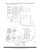


Table Of Contents
- Applications
- North American emissions compliance
- United States
- Canada
- Installation
- Parts included
- Location considerations
- Installing the thermostat controller
- Wiring
- Setup and adjustments
- Overview
- Customizing the home screen
- Touchscreen icons
- User lockout
- Using the USB port
- Loading the firmware
- Backing up the settings
- Restoring the settings
- Choosing the Communication mode (TEC3612 and TEC3613 Models)
- Configuring the network settings for wireless models
- Configuring the thermostat controller
- Installer configuration menu
- Screen reset
- Selecting the unit type
- By default, the thermostat controller is configured for four-pipe fan coil mode. To change to a two-pipe or Pressure-Dependent VAV mode:
- Selecting the heating and cooling device type
- Configuring the supply fan - fan coil only
- Setting the Control mode
- Setting the Fan mode - fan coil only
- Configuring the zone space or equipment size - units configured with floating actuators, multi- speed fans, and variable-speed fans only
- Changeover
- Dehumidification control - fan coil only
- Temperature setpoints
- Configuring occupancy
- Selecting schedule source
- Scheduling (for networked models)
- Setting the local schedule
- Overriding the Occupancy mode
- Enabling optimal start
- Enabling the motion sensor (TEC3x12, TEC3x13 Models)
- PID/PRAC+ automatic control tuning
- Configurable binary inputs
- Aux control
- Commissioning mode
- Configurable analog inputs (AIs)
- Configuring the AIs
- Networked sensors
- Availability of AIs
- Priority for configurable AIs
- Priority for overall sensors data sources
- Available fault diagnostics
- Menus and submenus
- Troubleshooting
- Repair information
- Technical specifications
- TEC3000 Series Networked and Wireless On/Off or Floating Fan Coil and Individual Zone Thermostat Controllers with Dehumidification Capability (Part 1 of 3)

TEC3000 Series Networked and Wireless On/Off or Floating Fan Coil and Individual Zone Thermostat Controllers
with Dehumidification Capability Installation Guide
19
Unit Power
On
Standby
Powers the thermostat controller on or off.
Notes:
• This icon disables all equipment control but does not physically power down
the unit.
• On the modern home screen, if the Unit Power icon is in standby mode, the
temperature and humidity are also displayed in standby mode to indicate
that control off or standby mode is active.
Humidity
On
Standby
Indicates the humidity reading.
Degree
On
Standby
Indicates that the unit is set to degrees.
Network Communication
(for Networked Models)
No Signal
Indicates that the thermostat controller detected a supervisory controller and both
are online.
Indicates that the thermostat controller did not detect a supervisory controller.
Radio Signal (for
Wireless Models)
No Signal
Low Signal
Medium Signal
High Signal
Indicates the strength of the radio signal.
Arrow Up
Arrow Down
Increases or decreases the cooling value on the home screen.
Arrow Up
Arrow Down
Increases or decreases the heating value on the home screen.
Table 5: Touchscreen icons (Part 2 of 5)
Icon Icon name Description