
Install Instructions


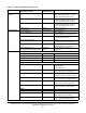
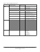

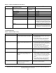
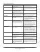
Table Of Contents
- Applications
- North American Emissions Compliance
- United States
- Canada
- Installation
- Parts Included
- Location Considerations
- Installing the Thermostat Controller
- Wiring
- Setup and Adjustments
- Overview
- Customizing the Home Screen
- Touchscreen Icons
- User Lockout
- Using the USB Port
- Loading the Firmware
- Backing Up the Settings
- Restoring the Settings
- Choosing the Communication Mode (TEC3620-00-000, TEC3621-00-000, TEC3622-00-000, and TEC3623-00-000 Models)
- Configuring the Thermostat Controller
- Installer Configuration Menu
- Screen Reset
- Selecting the Unit Type
- By default, the thermostat controller is configured for 4-pipe fan coil mode. To change to a 2-pipe or Pressure-Dependent VAV mode:
- Configuring the Supply Fan - Fan Coil Only
- Setting the Control Mode
- Setting the Fan Mode - Fan Coil Only
- Configuring the Zone Space or Equipment Size
- Changeover
- Dehumidification Control - Fan Coil Only
- Temperature Setpoints
- Configuring Occupancy
- Selecting Schedule Source
- Scheduling
- Setting the Local Schedule
- Overriding the Occupancy Mode
- Enabling Optimal Start
- Enabling the Motion Sensor (TEC3x21-00-000, TEC3x23-00-000 Models)
- PID/PRAC+ Automatic Control Tuning
- Configurable Binary Inputs
- Aux Control
- Commissioning Mode
- Sensor Priority
- Available Fault Diagnostics
- Menus and Submenus
- Troubleshooting
- Repair Information
- TEC3000 Series Proportional Fan Coil and Individual Zone Thermostat Controllers with Dehumidification Capability (Part 1 of 2)

TEC3000 Series Proportional Fan Coil and Individual Zone Thermostat Controllers with Dehumidification
Capability Installation Instructions
40
Dirty Filter Equipment connected to the BI
configured for a Dirty Filter alarm is
triggering the alarm.
Replace the filter in the equipment as explained in
the manufacturer's instructions.
Calibration Corrupt Factory calibration data is lost or is not
installed.
Order replacement units and return the affected
devices to Johnson Controls under the RMA
program.
Changeover Fail The Supply Temperature Sensor is not
installed, has failed, or has been
disconnected and the TEC can no
longer detect changeover mode to cool
or heat.
Follow the same steps as Supply Temp Fail
alarm.
Zone Temp Unreliable All sources of zone temperature are
unreliable, including the onboard
sensor.
Order replacement units and return the affected
devices to Johnson Controls under the RMA
program.
Open Window The switch connected to the BI
configured for Open Window is sensing
that the window is opened, and control
has shut down.
1. Close the window to resume control.
2. Check sensor functionality with an ohmmeter,
and verify the wiring to the TEC.
3. Order replacement units and return the
affected devices to Johnson Controls under
the RMA program.
Fan Lock The switch connected to the BI
configured for Fan Lock did not sense
airflow within 10 seconds of starting the
fan, and control has been shut down.
1. Inspect equipment to ensure fan functions.
2. Check sensor functionality with an ohmmeter,
and verify wiring to the TEC.
3. Reset fault by entering the menu, selecting
Fault Status, and selecting the Fan Lock.
4. If problems persist, order replacement units
and return the affected devices to Johnson
Controls under the RMA program.
Humidity Unreliable The zone humidity reading was reliable
and has now failed.
1. If the source of zone humidity was the
onboard sensor, contact Johnson Controls
product sales and support.
2. If the source of zone humidity was a BAS,
check the BAS to ensure that it is still online
and providing the TEC with the humidity
reading. If removal of the BAS mapping was
intentional, reset sensors through the menu.
Controller Fault The controller has detected an internal
fault that it cannot recover.
Order replacement units and return the affected
devices to Johnson Controls under the RMA
program.
An unknown error has prevented the
controller from turning on.
Order replacement units and return the affected
devices to Johnson Controls under the RMA
program.
Touchscreen Unavailable The touchscreen components have
failed to initialize.
1. Reboot the controller.
2. If problems persist, order replacement units
and return the affected devices to Johnson
Controls under the RMA program.
Board Mismatch The baseboard and CPU board are
paired incorrectly. An error message
appears on the TEC indicating the
model number of the baseboard and
CPU board.
Match the baseboard to its corresponding CPU
board. See Figure 5 for information on ensuring
that you have the CPU board and base board
paired correctly.
Table 11: Fault List (Part 2 of 3)
Faults Probable Causes Solutions