
Install Instructions
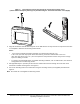
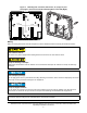


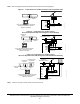
Table Of Contents
- Applications
- North American Emissions Compliance
- United States
- Canada
- Installation
- Parts Included
- Location Considerations
- Installing the Thermostat Controller
- Wiring
- Setup and Adjustments
- Overview
- Customizing the Home Screen
- Touchscreen Icons
- User Lockout
- Using the USB Port
- Loading the Firmware
- Backing Up the Settings
- Restoring the Settings
- Choosing the Communication Mode (TEC3620-00-000, TEC3621-00-000, TEC3622-00-000, and TEC3623-00-000 Models)
- Configuring the Thermostat Controller
- Installer Configuration Menu
- Screen Reset
- Selecting the Unit Type
- By default, the thermostat controller is configured for 4-pipe fan coil mode. To change to a 2-pipe or Pressure-Dependent VAV mode:
- Configuring the Supply Fan - Fan Coil Only
- Setting the Control Mode
- Setting the Fan Mode - Fan Coil Only
- Configuring the Zone Space or Equipment Size
- Changeover
- Dehumidification Control - Fan Coil Only
- Temperature Setpoints
- Configuring Occupancy
- Selecting Schedule Source
- Scheduling
- Setting the Local Schedule
- Overriding the Occupancy Mode
- Enabling Optimal Start
- Enabling the Motion Sensor (TEC3x21-00-000, TEC3x23-00-000 Models)
- PID/PRAC+ Automatic Control Tuning
- Configurable Binary Inputs
- Aux Control
- Commissioning Mode
- Sensor Priority
- Available Fault Diagnostics
- Menus and Submenus
- Troubleshooting
- Repair Information
- TEC3000 Series Proportional Fan Coil and Individual Zone Thermostat Controllers with Dehumidification Capability (Part 1 of 2)

TEC3000 Series Proportional Fan Coil and Individual Zone Thermostat Controllers with Dehumidification
Capability Installation Instructions
4
Figure 2: Removing the Security Screw from the Thermostat Controller Cover
(shown without Occupancy Sensor) (Left) and Removing the Thermostat Controller Cover (Right)
3. Align the thermostat controller mounting base on the wall with the security screw on the top and use the base
as a template to mark the two mounting hole locations.
Notes:
• If you need to install the thermostat controller on an electrical junction box, use
2-1/2 x 4 in. (63 x 101 mm) square boxes with mud ring covers and avoid smaller 1-1/2 x 4 in.
(38 x 101 mm) square or 3 x 2 in. (76 x 51 mm) boxes. This procedure ensures that you have enough
space for cabling, if needed.
• For surface-mounted applications, use durable mounting hardware, such as wall anchors, that cannot be
easily pulled out of the mounting surface.
4. Pull approximately 6 in. (152 mm) of wire from the wall and insert the wire through the center hole in the
thermostat controller mounting base. See Figure 3.
5. Secure the mounting base to the wall surface using two mounting screws (user supplied) as illustrated in
Figure 3.
Note: Be careful not to overtighten the mounting screws.
FIG:security screw
FIG:thermostat cover