
Install Instructions
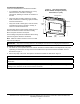
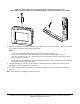
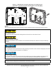
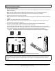
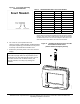

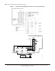
Table Of Contents
- Applications
- North American Emissions Compliance
- United States
- Canada
- Installation
- Parts Included
- Location Considerations
- Installing the Thermostat Controller
- Wiring
- Setup and Adjustments
- Overview
- Customizing the Home Screen
- Touchscreen Icons
- User Lockout
- Using the USB Port
- Loading the Firmware
- Backing Up the Settings
- Restoring the Settings
- Choosing the Communication Mode (TEC3620-00-000, TEC3621-00-000, TEC3622-00-000, and TEC3623-00-000 Models)
- Configuring the Thermostat Controller
- Installer Configuration Menu
- Screen Reset
- Selecting the Unit Type
- By default, the thermostat controller is configured for 4-pipe fan coil mode. To change to a 2-pipe or Pressure-Dependent VAV mode:
- Configuring the Supply Fan - Fan Coil Only
- Setting the Control Mode
- Setting the Fan Mode - Fan Coil Only
- Configuring the Zone Space or Equipment Size
- Changeover
- Dehumidification Control - Fan Coil Only
- Temperature Setpoints
- Configuring Occupancy
- Selecting Schedule Source
- Scheduling
- Setting the Local Schedule
- Overriding the Occupancy Mode
- Enabling Optimal Start
- Enabling the Motion Sensor (TEC3x21-00-000, TEC3x23-00-000 Models)
- PID/PRAC+ Automatic Control Tuning
- Configurable Binary Inputs
- Aux Control
- Commissioning Mode
- Sensor Priority
- Available Fault Diagnostics
- Menus and Submenus
- Troubleshooting
- Repair Information
- TEC3000 Series Proportional Fan Coil and Individual Zone Thermostat Controllers with Dehumidification Capability (Part 1 of 2)

TEC3000 Series Proportional Fan Coil and Individual Zone Thermostat Controllers with Dehumidification
Capability Installation Instructions
3
Location Considerations
Locate the TEC3000 Series Thermostat Controller:
• on a partitioning wall, approximately 5 ft (1.5 m)
above the floor in a location of average
temperature, allowing for vertical air circulation to
the TEC
• away from direct sunlight, radiant heat, outside
walls, outside doors, air discharge grills, stairwells,
and from behind doors
• away from steam or water pipes, warm air stacks,
unconditioned areas (not heated or cooled), or
sources of electrical interference
For integrated passive infrared (PIR) models, be sure
that the thermostat controller is located centrally,
where occupant movement is frequent.
Use insulating foam pads for installations where wiring
passes through the wall to the thermostat.
Note: Allow for sufficient clearance to insert a USB
drive into the USB port.
Installing the Thermostat Controller
1. Use a 1/16 in. (1.5 mm) Allen wrench or Johnson Controls® T-4000-119 Allen-Head Adjustment Tool (order
separately) to remove the security screw if it is installed on the top of the thermostat controller cover as
illustrated in Figure 2.
2. Pull the top edge of the cover and open the thermostat controller as illustrated in Figure 2.
IMPORTANT: Only connect memory devices to the USB port. Do not use it for charging external devices.
IMPORTANT: The cover is not secured on the bottom. Be careful not to drop the cover.
IMPORTANT: If you are installing more than one thermostat controller, keep track of which cover attaches to
which base.
IMPORTANT: Use proper Electrostatic Discharge (ESD) precautions during installation and servicing to avoid
damage to the electronic circuits of the thermostat controller.
Figure 1: Thermostat Controller
Shown without Occupancy Sensor,
Dimensions, in. (mm)
FIG:thermostat features
USB Port
Display
Security Screw
1-13/32
(36)
4-23/32
(120)
5-5/8
(143)