*24107880E* 24-10788-0, Rev. E (barcode for factory use only) TEC3000 Series Proportional Fan Coil and Individual Zone Thermostat Controllers with Dehumidification Capability Part No. 24-10788-0, Rev. E Installation Instructions TEC3320-xx-xxx, TEC3321-xx-xxx, TEC3322-xx-xxx, TEC3323-xx-xxx, TEC3620-xx-xxx, TEC3621-xx-xxx, TEC3622-xx-xxx, TEC3623-xx-xxx Issued July 2018 Refer to the QuickLIT website for the most up-to-date version of this document.
IMPORTANT: The TEC3000 Series Thermostat Controller is intended to provide an input to equipment under normal operating conditions. Where failure or malfunction of the thermostat controller could lead to personal injury or property damage to the controlled equipment or other property, additional precautions must be designed into the control system.
Location Considerations Locate the TEC3000 Series Thermostat Controller: • • on a partitioning wall, approximately 5 ft (1.
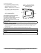
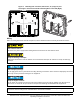
FIG:security screw FIG:thermostat cover Figure 2: Removing the Security Screw from the Thermostat Controller Cover (shown without Occupancy Sensor) (Left) and Removing the Thermostat Controller Cover (Right) 3. Align the thermostat controller mounting base on the wall with the security screw on the top and use the base as a template to mark the two mounting hole locations. Notes: • If you need to install the thermostat controller on an electrical junction box, use 2-1/2 x 4 in.
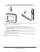
Figure 3: Mounting Hole Locations, Dimensions, in. (mm) (Left) and Securing the Thermostat Controller Mounting Base to the Wall (Right) 4-1/16 (103) FIG:TEC Backplane1 FIG:TEC Backplane2 3-1/4 (83) Wiring When an existing thermostat controller is replaced, remove and label the wires to identify the terminal functions. Risk of Electric Shock. Disconnect the power supply before making electrical connections to avoid electric shock. Risque de décharge électrique.
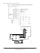
IMPORTANT: Use proper ESD precautions during installation and servicing to avoid damage to the electronic circuits of the thermostat controller. To wire the thermostat controller: 1. Strip the ends of each wire 1/4 in. (6 mm) and connect them to the appropriate screw terminals as indicated in Table 2 and Figure 7. Note: For more details on wiring the MS/TP Communications Bus, refer to the TEC3000 Series and Field-Selectable BACnet® MS/TP or N2 Networked Thermostat Controllers (LIT-12011956). 2.
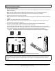
Figure 5: Error Code Indicating Mismatched Boards CPU Board Base Board Table 1: TEC3000 Model Names and Code Numbers Name Code Number1 Name Code Number1 TEC3310 00 TEC3610 0A TEC3311 01 TEC3611 0B TEC3312 02 TEC3612 0C TEC3313 03 TEC3613 0D TEC3320 04 TEC3620 0E TEC3321 05 TEC3621 0F TEC3322 06 TEC3622 10 TEC3323 07 TEC3623 11 TEC3330 08 TEC3630 12 TEC3331 09 TEC3631 13 1.
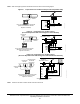
Table 2: Terminal Identification (See Figure 7 for Wiring Diagram) Terminal Label Function TEC3320, TEC3321, TEC3322, TEC3323, Proportional FC/VAV TEC3620, TEC3621, TEC3622, TEC3623 Proportional FC/VAV 24 V 24 VAC hot from transformer FAN H Fan high FAN M Fan medium FAN L Fan low and fan on AUX Auxiliary binary output AUX Auxiliary power COM1 24 VAC common from transformer CLG Cooling command (configurable 0 to 10 V range) NC No connection HTG COM Heating command (configurable 0 to 10
Note: Only one transformer is required for each TEC.
Note: VAV and 2-pipe systems should connect their valve to the heating output.
Note: VAV and 2-pipe systems should connect their valve to the heating output.
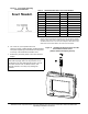
Figure 15: Binary Input Wiring Dry Contact BI1 Bi2 FIG:Binary Input Wiring Dry Contact Setup and Adjustments IMPORTANT: Table 10 provides a full list of TEC3000 menu settings. In the upcoming sections, step-by-step instructions are included on how to access and adjust the more commonly used menus. Overview Figure 16 shows the thermostat controller home screen. You can customize it to show or hide various elements from the occupant.
3. Enable or disable elements of the home screen as appropriate for the building owner and occupants. 4. Set the passcode on the thermostat controller to prevent the occupants from changing settings that they should not have access to change. Touchscreen Icons Table 3 describes the home screen touchable icons. Press and release a touchscreen icon to activate the TEC. Additional touchable icons appear based on the menu, and those icons are also described in Table 3.
Table 3: Touchscreen Icons (Part 2 of 3) Icon Icon Name Description Fan Overrides for Single-speed Fans Adjusts the fan override between On, Auto, and Quiet for single-speed fans. On Auto Quiet Fan Overrides for Variable-speed Fans Adjusts the fan override between On, Auto, and Quiet for variable-speed fans. On Auto Quiet Fan Overrides for Multi-speed Fans Adjusts the fan override between Low, Medium, High, Auto, and Quiet for multi-speed fans.
Table 3: Touchscreen Icons (Part 3 of 3) Icon Icon Name Description Clears the password entry on the keypad screen. Clear Indicates that the value is editable. Wrench Indicates that an event or schedule is programmed for a specific day of the week. Checkmark Indicates that an error has occurred. Exclamation Point User Lockout You can select from three different levels of access at the local display to manage functionality through the supervisory controller.
8. Remove the USB drive from the TEC3000 controller when the update is complete. The TEC3000 firmware update is complete when the TEC3000 restarts and returns to the home screen. Backing Up the Settings 1. Ensure that the TEC screen is on. 2. Insert the USB drive into the right side of the TEC. See Figure 1 for the USB port location. 3. Press the Menu icon. 4. Scroll down the menu and press Update. 5. Press Backup. A message appears stating that the file is saved locally and on a USB drive. 6.
8. Press BACnet Instance ID. 9. Enter the unique BACnet instance ID through the keypad. 10. Press Save. 11. Press to return to the previous screen. 12. Press BACnet Address. 13. Enter the BACnet MS/TP address through the keypad. 14. Press Save. 15. After selecting N2 in Step 5, press Save. 16. Press to return to the previous screen. 17. Press N2 Address. 18. Enter the N2 address through the keypad. 19. Press Save.
2. Press Equipment Setup. 3. Press General. 4. Press Unit Type and select 2-pipe, 4-pipe, or VAV. 5. Press to save and to return to the previous screen. Note: Selecting VAV reboots the controller in order to apply the change. Configuring the Supply Fan - Fan Coil Only On fan coil units (2-pipe or 4-pipe), three different types of supply fans are supported.
4. Press Start Voltage and adjust accordingly. 5. Press Full Speed Voltage and adjust accordingly. 6. Press Minimum Command and adjust accordingly. 7. Press to save and to return to the previous screen. Setting the Control Mode The Control Mode informs the controller to either run in Cooling only, Heating only, or Automatic mode, based on the temperature in the zone relative to the heating and cooling setpoints. Control Mode does not override equipment lockouts or changeover. To set the Control Mode: 1.
• High—Fan is continuously on high • Auto—Follows the behavior set as Fan Mode • Quiet—Follows the behavior set as Fan Mode, but prevents the fan from ever going above minimum speed To set the Fan Mode: 1. Press the Menu icon. 2. Press Control Setup. 3. Press General. 4. Press Fan Mode and select On, Auto, or Smart. 5. Press to save and to return to the previous screen.
7. Press to save and to return to the previous screen. Additionally, the thermostat controller supports manual changeover. To configure manual changeover: 1. Press the Menu icon. 2. Press Equipment Setup. 3. Press Changeover. 4. Press Changeover Mode and select Heating or Cooling. 5. Press to save and to return to the previous screen. You need to ensure that the Supply Temp type is set to Analog Sensor.
4. Press to save and to return to the previous screen. This point is also exposed to the BAS through the point DEHUM-SP. Temperature Setpoints The thermostat controller provides a flexible setpoint configuration to give power to the building owner while being easy to use by the occupant. In addition to a simple up/down offset adjustment on the home screen for the occupant, there are six temperature setpoints on the TEC.
Table 5: Setpoint Operation Mode of Setpoint Operation Details Occ Setpoint Select = Setpoint Offset and Heat Cool Setpoint Mode = Common Setpoint In this mode, the TEC has one setpoint, Common Setpoint, for heating and cooling. There is also a common Setpoint Offset (warmer/cooler adjust) that is only applied to Common Setpoint. Otherwise, this setting works the same as when Occ Setpoint Select = Setpoint Offset and Heat Cool Setpoint Mode = Individual Setpoints.
Table 6: Occupancy Determination Sequence of Operation (Highest to Lowest Priority) Manual Occupancy Mode (OCCOVRD -MODE) Occupancy BI (BI1-S, BI2-S)1 Temporary Occupancy2, Occupied – – 3 Status Indicated Occupancy Schedule (External or Schedule) (OCCCONFIG, NET-OCC) Motion Sensor4 Effective Occupancy (EFF-OCC) Occupancy Source (OCCSOURCE-S) – – OccupiedOverride Occ Override Unoccupied No Override UnoccupiedOverride Closed1 Occupied Open1 Unoccupied Not Configured1 True2 NOT Occupied
Once the Occupancy Schedule command is set, the effective occupancy is determined by settings shown in the Occupancy Determination table. See Table 6. Table 7: BAS Objects for Scheduling BAS Objects for Scheduling OCC-CONFIG LOCAL-OCC (Commanded by Internal Schedule) NET-OCC External Any State (Internal Schedule in Control) Occupied Occupied Unoccupied Unoccupied Standby Standby Not Set Not Set Not Applicable Occupied Schedule 1.
7. Set the Occupancy to Not Set, Occupied, Unoccupied, or Standby and press Save. IMPORTANT: Internally, the TEC 3000 uses a BACnet schedule where daily schedules are independent of the previous and next days. The default occupancy of the TEC3000 from the factory is set to Occupied. As a result, a daily event at 12:00 AM must be scheduled if you do not want the controller to transition to Occupied Mode at midnight.
9. Press Save to save the event and press the Return icon to return to the main scheduler screen. Figure 20: Returning to the Main Menu 10. Press to save and to return to the previous screen. Overriding the Occupancy Mode The TEC supports a manual override of all other schedule sources (for example, Schedule, Occupancy BI, and temporary occupancy). To override the Occupancy Mode: 1. Press the Menu icon. 2. Press Schedule. 3. Press Schedule Options. 4.
Enabling the Motion Sensor (TEC3x21-00-000, TEC3x23-00-000 Models) By default on models with integral motion sensing capability, the motion sensor is enabled with a default timeout of 15 minutes from the last detection of motion in the zone. On models without an integrated sensor, the default timeout is still 15 minutes, but it only is applied when one of the two configurable binary inputs is set to be a motion sensor (see Configurable Binary Inputs for information on configuring the binary inputs).
Table 8: TEC3000 Tuning Types Tuning Type Description Deadband Override There is no deadband in use with proportional devices. This operates in the same way as Automatic PID tuning. Manual PID Tuning Manual tuning of Heating and Cooling PIDs. The manual tuning parameters are listed under Control Setup > Tuning in Table 10. Note: For more details on PID/PRAC+ Automatic Control Tuning, refer to the Controller Tool Help (LIT-12011147).
Table 9: Input Polarities BI Configuration Contact Open Contact Closed Fan Lock No Airflow Airflow Open Door Door Open, Unoccupied Door Closed, Occupied Open Window Window Open, Control Shut Down Window Closed, Control Running Supply Fan Status Supply Fan Off Supply Fan On 1. Configurations that support both BIs configured for the same feature of the action that occurs when either of the BIs enter that state.
Individual outputs can be commanded through this interface. For binary outputs, the options are Off or On; for analog outputs, they can be commanded from 0 to 100%. Whenever a control output is turned on, the fan is engaged for safety purposes. To command an output from the Commissioning menu: 1. Select the output to command. Adjust the value to the desired output and press Save. The output immediately changes to that value. 2.
Menus and Submenus In the following table, the * indicates that the menus depend on your configuration.
Table 10: Menus and Submenus (Part 2 of 8) Level 1 Level 2 (LCD Screen Name) Schedule Schedule Options Display Settings Control Setup Level 3 (Default Values) Available Values1 Set Schedule — See Scheduling Optimal Start Enable No Yes or No Temp Occ Duration 120 minutes 0 to 300 minutes Motion Sensor Timeout 15 minutes 15 to 240 minutes Manual Occupancy Mode No Override No Override, Occupied, Unoccupied Schedule Source Local Local or BAS Passcode Enable No Yes or No Passcode* N
Table 10: Menus and Submenus (Part 3 of 8) Level 1 Level 2 (LCD Screen Name) Level 3 (Default Values) Available Values1 Control Setup (Cont) Fan Off Delay* 30 seconds 0 to 120 seconds * Fan coil units only Frost Protection Yes Yes or No Dehumidification Enable* No Yes or No * Fan coil units with humidity sensor Aux Mode Not Used Not Used, Occupied NO, Occupied NC, Occupied Fan NO, Occupied Fan NC, On, Off Load Shed Rate Limit 0.066°F 0 to 1°F (0 to 0.
Table 10: Menus and Submenus (Part 4 of 8) Level 1 Level 2 (LCD Screen Name) Level 3 (Default Values) Available Values1 Control Setup (Cont) Zone Temp Alarm Enabled No Yes or No Zone Temp Low Limit 55°F 32 to 150°F (0 to 65.56°C) Zone Temp High Limit 90°F 32 to 150°F (0 to 65.56°C) Temp Control Setup Automatic PID Tuning Automatic PID Tuning, Manual PID Tuning, Deadband Override Reset PID Tuning No Yes or No Deadband* 0.7 to 1.5°F 1.0°F (-17.
Table 10: Menus and Submenus (Part 5 of 8) Level 1 Level 2 (LCD Screen Name) Level 3 (Default Values) Available Values1 Control Setup (Cont.) Cool Time Constant* 720 seconds 360 to 1,440 seconds *Values only appear when the Temp control equals Manual PID Tuning. Cool Process Dead Time* 72 seconds 20 to 120 seconds *Values only appear when the Temp control equals Manual PID Tuning. Cool Period* 60 seconds 30 to 120 seconds *Values only appear when the Temp control equals Manual PID Tuning.
Table 10: Menus and Submenus (Part 6 of 8) Level 1 Level 2 (LCD Screen Name) Level 3 (Default Values) Available Values1 Equipment Setup (Cont) Reheat Min On Time* 180 seconds 0 to 360 second * Reheat installed Reheat/ Min Off Time* 180 seconds 0 to 360 seconds * Reheat installed Changeover Mode* Auto Auto, Cooling, or Heating * Non 4-Pipe units Supply Temp Type* Analog Sensor Analog Sensor, Heating NC, Cooling NC * Changeover Mode = Auto Changeover Setpoint* 55°F 40 to 200°F (4 to 93°C) *
Table 10: Menus and Submenus (Part 7 of 8) Level 1 Level 2 (LCD Screen Name) Level 3 (Default Values) Available Values1 System Status (Cont) Unit Status Cooling System Fault Airflow Fault Open Window Control Off Unreliable Temperature Dehumidification Idle Cooling Heating Cooling Unavailable Heating Unavailable Cooling Unavailable due to Changeover Cooling Unavailable due to OA Temp Cooling Unavailable due to Control Mode Heating Unavailable due to Changeover Heating Unavailable due to OA Temp Heatin
Table 10: Menus and Submenus (Part 8 of 8) Level 1 Level 2 (LCD Screen Name) Level 3 (Default Values) Available Values1 Commissioning Supply Air Temperature Display Current Temperature — Heat Command 0% 0 to 100% Cool Command 0% 0 to 100% Supply Fan No Yes or No Aux No Yes or No View Version x.x.x.xxxx Current Release of Software Update 1.
Table 11: Fault List (Part 2 of 3) Faults Probable Causes Solutions Dirty Filter Equipment connected to the BI configured for a Dirty Filter alarm is triggering the alarm. Replace the filter in the equipment as explained in the manufacturer's instructions. Calibration Corrupt Factory calibration data is lost or is not installed. Order replacement units and return the affected devices to Johnson Controls under the RMA program.
Table 11: Fault List (Part 3 of 3) Faults Probable Causes Solutions Firmware Mismatch The previous upgrade has not completed. 1. Upgrade the TEC3000 to the latest released version. 2. Upgrade the TEC3000 to the current version again. The previous downgrade has not completed because the previous version is no longer supported. Reboot the TEC3000 to clear the fault. USB Malfunction A USB drive has malfunctioned and drawn more than the maximum allowed current. 1.
Table 12: Troubleshooting Details1 (Part 1 of 2) Symptom Probable Causes Solutions The controller displays Idle with a Unit Status of Cooling Unavailable due to Changeover despite being above cooling setpoint, or with a status of Heating Unavailable due to Changeover despite being below the setpoint. The 2-pipe fan coil/VAV system does not have a changeover sensor and switch connected, or the sensor/switch has failed. 1. Check the wiring of the supply temperature sensor or switch. 2.
Table 12: Troubleshooting Details1 (Part 2 of 2) Symptom Probable Causes Solutions The controller is unable to access a USB drive. The drive is formatted as NTFS or another unsupported format. The TEC supports FAT and FAT32 formats only. Reformat the USB drive, or try a different USB drive with a supported format. The USB drive is defective. Try a different USB drive. The I/O board that the display board is currently attached to does not match the one that initially shipped with the display board.
TEC3000 Series Proportional Fan Coil and Individual Zone Thermostat Controllers with Dehumidification Capability (Part 2 of 2 ) Auxiliary Output Rating/Triac Output 19 to 30 VAC, 1.0 A maximum, 15 mA minimum, 3.0 A in-rush Binary Inputs Dry contact across terminal COM to terminals BI1, BI2, or COS Analog Inputs Nickel, platinum, A99B, 2.25k ohm NTC, 10k ohm NTC, 10k ohm NTC Type 3 across terminal COM to terminals R SEN or COS Temperature Sensor Type Local 1k ohm platinum sensor Wire Size 18 AWG (1.
European Single Point of Contact: NA/SA Single Point of Contact: APAC Single Point of Contact: JOHNSON CONTROLS WESTENDHOF 3 45143 ESSEN GERMANY JOHNSON CONTROLS 507 E MICHIGAN ST MILWAUKEE WI 53202 USA JOHNSON CONTROLS C/O CONTROLS PRODUCT MANAGEMENT NO. 22 BLOCK D NEW DISTRICT WUXI JIANGSU PROVINCE 214142 CHINA Building Technologies & Solutions 507 E. Michigan Street, Milwaukee, WI 53202 Metasys® and Johnson Controls® are registered trademarks of Johnson Controls.