
Install Instructions
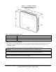
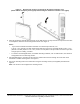
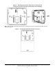
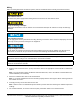

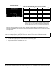
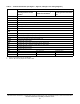
Table Of Contents
- Applications
- North American emissions compliance
- United States
- Canada
- Installation
- Parts included
- Location considerations
- Installing the thermostat controller
- Wiring
- Setup and adjustments
- Overview
- Customizing the home screen
- Touchscreen icons
- User lockout
- Using the USB port
- Loading the firmware
- Backing up the settings
- Restoring the settings
- Choosing the Communication mode (TEC3612 and TEC3613 Models)
- Configuring the network settings for wireless models
- Configuring the thermostat controller
- Installer configuration menu
- Screen reset
- Selecting the unit type
- By default, the thermostat controller is configured for four-pipe fan coil mode. To change to a two-pipe or Pressure-Dependent VAV mode:
- Selecting the heating and cooling device type
- Configuring the supply fan - fan coil only
- Setting the Control mode
- Setting the Fan mode - fan coil only
- Configuring the zone space or equipment size - units configured with floating actuators, multi- speed fans, and variable-speed fans only
- Changeover
- Dehumidification control - fan coil only
- Temperature setpoints
- Configuring occupancy
- Selecting schedule source
- Scheduling (for networked models)
- Setting the local schedule
- Overriding the Occupancy mode
- Enabling optimal start
- Enabling the motion sensor (TEC3x12, TEC3x13 Models)
- PID/PRAC+ automatic control tuning
- Configurable binary inputs
- Aux control
- Commissioning mode
- Configurable analog inputs (AIs)
- Configuring the AIs
- Networked sensors
- Availability of AIs
- Priority for configurable AIs
- Priority for overall sensors data sources
- Available fault diagnostics
- Menus and submenus
- Troubleshooting
- Repair information
- Technical specifications
- TEC3000 Series Networked and Wireless On/Off or Floating Fan Coil and Individual Zone Thermostat Controllers with Dehumidification Capability (Part 1 of 3)

TEC3000 Series Networked and Wireless On/Off or Floating Fan Coil and Individual Zone Thermostat Controllers
with Dehumidification Capability Installation Guide
9
6. Use a 1/16 in. (1.5 mm) Allen wrench or Johnson Controls T-4000-119 Allen-Head Adjustment Tool (order
separately) to reinstall the security screw on the top of the thermostat controller cover. See Figure 2 for security
screw placement.
7. Remove the protective plastic cover sheet from the display.
Notes:
• For VAV and two-pipe systems, connect the valve to the heating output.
• Only one transformer is required for each TEC.
• Power to the AUX contact comes from the reheat coil.
Table 3: TEC3000 model names and code numbers
Name
Code number
1
1. The two-character code number is listed within the error code to
indicate that the CPU board and base board do not belong together.
However, if the same code number appears as both the CPU board
and base board, there is no error. For example, if 0C is listed as the
CPU board and the base board, the model is the TEC3612.
Name
Code number
1
TEC3012 22 TEC3323 07
TEC3013 23 TEC3330 08
TEC3022 26 TEC3331 09
TEC3023 27 TEC3612 0C
TEC3030 28 TEC3613 0D
TEC3031 29 TEC3622 10
TEC3312 02 TEC3623 11
TEC3313 03 TEC3630 12
TEC3322 06 TEC3631 13
IMPORTANT: If the display is dirty, gently wipe it clean with isopropyl alcohol or ethyl alcohol. Do not scrub
hard as to avoid damaging the surface. Do not use other cleaners such as water, ketones, and aromatic
solvents, since they may damage the polarizer.
Figure 6: Error code indicating
mismatched boards