
Install Instructions
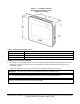
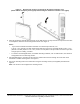
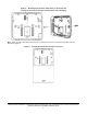

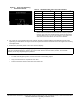
Table Of Contents
- Applications
- North American emissions compliance
- United States
- Canada
- Installation
- Parts included
- Location considerations
- Installing the thermostat controller
- Wiring
- Setup and adjustments
- Overview
- Customizing the home screen
- Touchscreen icons
- User lockout
- Using the USB port
- Loading the firmware
- Backing up the settings
- Restoring the settings
- Choosing the Communication mode (TEC3612 and TEC3613 Models)
- Configuring the network settings for wireless models
- Configuring the thermostat controller
- Installer configuration menu
- Screen reset
- Selecting the unit type
- By default, the thermostat controller is configured for four-pipe fan coil mode. To change to a two-pipe or Pressure-Dependent VAV mode:
- Selecting the heating and cooling device type
- Configuring the supply fan - fan coil only
- Setting the Control mode
- Setting the Fan mode - fan coil only
- Configuring the zone space or equipment size - units configured with floating actuators, multi- speed fans, and variable-speed fans only
- Changeover
- Dehumidification control - fan coil only
- Temperature setpoints
- Configuring occupancy
- Selecting schedule source
- Scheduling (for networked models)
- Setting the local schedule
- Overriding the Occupancy mode
- Enabling optimal start
- Enabling the motion sensor (TEC3x12, TEC3x13 Models)
- PID/PRAC+ automatic control tuning
- Configurable binary inputs
- Aux control
- Commissioning mode
- Configurable analog inputs (AIs)
- Configuring the AIs
- Networked sensors
- Availability of AIs
- Priority for configurable AIs
- Priority for overall sensors data sources
- Available fault diagnostics
- Menus and submenus
- Troubleshooting
- Repair information
- Technical specifications
- TEC3000 Series Networked and Wireless On/Off or Floating Fan Coil and Individual Zone Thermostat Controllers with Dehumidification Capability (Part 1 of 3)

TEC3000 Series Networked and Wireless On/Off or Floating Fan Coil and Individual Zone Thermostat Controllers
with Dehumidification Capability Installation Guide
7
Wiring
When an existing thermostat controller is replaced, remove and label the wires to identify the terminal functions.
To wire the thermostat controller, complete the following steps:
1. Strip the ends of each wire 1/4 in. (6 mm) and connect them to the appropriate screw terminals as indicated in
Table 4.
Note: For more details on wiring the MS/TP Communications Bus, refer to the MS/TP Communications Bus
Technical Bulletin (LIT-12011034).
2. Attach the communication wires to the terminal block.
Note: If you insert multiple wires into the terminals, properly twist the wires together before inserting them into
the terminal connectors.
3. Carefully push any excess wire back into the wall.
Note: Seal the hole in the wall with fireproof material to prevent drafts from affecting the ambient temperature
readings.
4. For networked models, set the bus end-of-line (EOL) termination switch to the desired location.
Risk of Electric Shock.
Disconnect the power supply before making electrical connections to avoid electric shock.
Risque de décharge électrique.
Débrancher l'alimentation avant de réaliser tout raccordement électrique afin d'éviter tout risque de décharge
électrique.
Risk of Property Damage.
Do not apply power to the system before checking all wiring connections. Short circuited or improperly connected
wires may result in permanent damage to the equipment.
Risque de dégâts matériels.
Ne pas mettre le système sous tension avant d'avoir vérifié tous les raccords de câblage. Des fils formant un
court-circuit ou connectés de façon incorrecte risquent d'endommager irrémédiablement l'équipement.
IMPORTANT: Make all wiring connections in accordance with local, national, and regional regulations. Do not
exceed the electrical ratings of the TEC3000 Series Thermostat Controller.
IMPORTANT: Use proper ESD precautions during installation and servicing to avoid damage to the electronic
circuits of the thermostat controller.