
Install Instructions

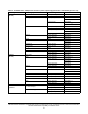


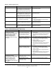
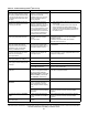
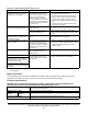
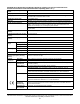

Table Of Contents
- Applications
- North American emissions compliance
- United States
- Canada
- Installation
- Parts included
- Location considerations
- Installing the thermostat controller
- Wiring
- Setup and adjustments
- Overview
- Customizing the home screen
- Touchscreen icons
- User lockout
- Using the USB port
- Loading the firmware
- Backing up the settings
- Restoring the settings
- Choosing the Communication mode (TEC3612 and TEC3613 Models)
- Configuring the network settings for wireless models
- Configuring the thermostat controller
- Installer configuration menu
- Screen reset
- Selecting the unit type
- By default, the thermostat controller is configured for four-pipe fan coil mode. To change to a two-pipe or Pressure-Dependent VAV mode:
- Selecting the heating and cooling device type
- Configuring the supply fan - fan coil only
- Setting the Control mode
- Setting the Fan mode - fan coil only
- Configuring the zone space or equipment size - units configured with floating actuators, multi- speed fans, and variable-speed fans only
- Changeover
- Dehumidification control - fan coil only
- Temperature setpoints
- Configuring occupancy
- Selecting schedule source
- Scheduling (for networked models)
- Setting the local schedule
- Overriding the Occupancy mode
- Enabling optimal start
- Enabling the motion sensor (TEC3x12, TEC3x13 Models)
- PID/PRAC+ automatic control tuning
- Configurable binary inputs
- Aux control
- Commissioning mode
- Configurable analog inputs (AIs)
- Configuring the AIs
- Networked sensors
- Availability of AIs
- Priority for configurable AIs
- Priority for overall sensors data sources
- Available fault diagnostics
- Menus and submenus
- Troubleshooting
- Repair information
- Technical specifications
- TEC3000 Series Networked and Wireless On/Off or Floating Fan Coil and Individual Zone Thermostat Controllers with Dehumidification Capability (Part 1 of 3)

TEC3000 Series Networked and Wireless On/Off or Floating Fan Coil and Individual Zone Thermostat Controllers
with Dehumidification Capability Installation Guide
53
Repair information
If the TEC3000 Series Thermostat Controller fails to operate within its specifications, replace the unit. For a
replacement thermostat controller, contact the nearest Johnson Controls representative.
Technical specifications
Partial Restore Complete is
displayed when trying to restore
settings from a backup file.
Not all of the items in the backup
file have been restored. This
error can be caused by a value
being out of the minimum or
maximum range in the backup
file. It may also occur if there are
inconsistencies in the reliability of
a setting in the backup file and on
the TEC device.
1. Create a Backup file on a USB drive for the
TEC that is showing the issue.
2. Edit the backup file created in the previous
step on a PC to reflect the desired settings.
3. Verify that the modified values are within
minimum and maximum range in the backup
file.
4. Restore the settings from the newly edited
backup file on the TEC.
The temperature displayed is lower
than the actual room temperature.
Cold air drafts are entering the
back of the TEC.
Seal any holes behind the TEC to reduce drafts.
Air is being forced through the
TEC from a nearby vent.
Move the location of the TEC or change the
venting to prevent air from being forced through
the TEC.
For networked models, the
Online icon does not appear for a
networked controller.
There is improper field bus
wiring.
Refer to the MS/TP Communications Bus
Technical Bulletin (LIT-12011034).
For wireless models, Supervisory
Status = Offline
The supervisory controller is not
communicating with the TEC.
The TEC is not mapped to a JCI
Supervisory System. The WNC
Gateway is not communicating
with the TEC.
1. Map the TEC into a JCI Supervisory system.
2. Verify that the PAN’s WNC Gateway is online.
3. Add ZFR Pro Routers/Repeaters into the
wireless system.
Some icons are hidden. Lockout levels are used or the
icons are hidden due to the
display settings.
See Table 6 for lockout levels and access details.
The touchscreen is unresponsive. You tap the display or touch the
controller within 5 mm of the
display when power is applied to
the controller.
Reboot the controller. Do not interact with the
controller until the home screen displays.
You do not tap the touchscreen, but
the display acts as if it is tapped,
which causes the display to blink or
toggle between screens.
You need to tap the display at an
offset from a touch point to activate
the display.
1. For common MS/TP troubleshooting information, refer to the MS/TP Communications Bus Technical Bulletin
(LIT-12011034).
TEC3000 Series Networked and Wireless On/Off or Floating Fan Coil and Individual Zone
Thermostat Controllers with Dehumidification Capability (Part 1 of 3 )
Power requirements 19 to 30 VAC, 50/60 Hz, 4 VA at 24 VAC nominal, Class 2 or
safety extra-low voltage (SELV)
USB port power rating 120 to 250 mA current draw supported
Relay contact
rating
On/off or floating
control
19 to 30 VAC, 1.0 A maximum, 15 mA minimum, 3.0 A in-rush, Class 2 or SELV
Fan relay output rating 19 to 30 VAC, 1.0 A maximum, 15 mA minimum, 3.0 A in-rush
Table 16: Troubleshooting details
1
(Part 3 of 3)
Symptom Probable causes Solutions