
Install Instructions

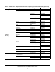


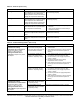
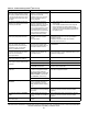
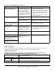
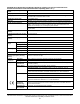

Table Of Contents
- Applications
- North American emissions compliance
- United States
- Canada
- Installation
- Parts included
- Location considerations
- Installing the thermostat controller
- Wiring
- Setup and adjustments
- Overview
- Customizing the home screen
- Touchscreen icons
- User lockout
- Using the USB port
- Loading the firmware
- Backing up the settings
- Restoring the settings
- Choosing the Communication mode (TEC3612 and TEC3613 Models)
- Configuring the network settings for wireless models
- Configuring the thermostat controller
- Installer configuration menu
- Screen reset
- Selecting the unit type
- By default, the thermostat controller is configured for four-pipe fan coil mode. To change to a two-pipe or Pressure-Dependent VAV mode:
- Selecting the heating and cooling device type
- Configuring the supply fan - fan coil only
- Setting the Control mode
- Setting the Fan mode - fan coil only
- Configuring the zone space or equipment size - units configured with floating actuators, multi- speed fans, and variable-speed fans only
- Changeover
- Dehumidification control - fan coil only
- Temperature setpoints
- Configuring occupancy
- Selecting schedule source
- Scheduling (for networked models)
- Setting the local schedule
- Overriding the Occupancy mode
- Enabling optimal start
- Enabling the motion sensor (TEC3x12, TEC3x13 Models)
- PID/PRAC+ automatic control tuning
- Configurable binary inputs
- Aux control
- Commissioning mode
- Configurable analog inputs (AIs)
- Configuring the AIs
- Networked sensors
- Availability of AIs
- Priority for configurable AIs
- Priority for overall sensors data sources
- Available fault diagnostics
- Menus and submenus
- Troubleshooting
- Repair information
- Technical specifications
- TEC3000 Series Networked and Wireless On/Off or Floating Fan Coil and Individual Zone Thermostat Controllers with Dehumidification Capability (Part 1 of 3)

TEC3000 Series Networked and Wireless On/Off or Floating Fan Coil and Individual Zone Thermostat Controllers
with Dehumidification Capability Installation Guide
52
The staged equipment shuts off
above the cooling setpoint or below
the heating setpoint when the PID
is running on the TEC. If the unit is
in On/Off Control mode, this does
not apply.
The PID control algorithm
minimizes overshoot and energy
usage for the particular
equipment and zone, and may
cycle the equipment prior to
reaching setpoint.
Expected behavior.
The staged equipment cycles too
rapidly or too slowly when the PID
is running on the TEC.
The control band around the
setpoint is determined by the
minimum on/off times and is set
incorrectly for the equipment,
zone, or user preference. There
is a tradeoff between reduced
control band size and increased
energy usage and equipment
wear from increased cycling.
1. Verify that equipment minimum on/off times are
set correctly.
2. If the default deadband around the setpoint
does not provide the desired temperature
control, set Temp Control Setup to Deadband
Override and set the Deadband parameter to
the desired value.
The controller provides an error
when trying to upgrade firmware.
The firmware on the USB drive is
below the minimum required
version.
Error code 1025.
Please use firmware version 3.0.2.xxxx (for
networked models) or 2.0.2.xxxx (for wireless
models) or higher.
A reboot is required to clear the Firmware
Mismatch fault that occurs.
The TEC3000 zone temperature
does not change fast enough
compared to the measured zone
temperature from a verification
device (a calibrated sensor).
The TEC3000 is configured by
default for larger spaces with
normal-sized equipment when a
proportional device is active.
Select Control Setup >Tuning > Equipment Size
> Oversized.
The zone space temperature
increases or decreases too much
when the unit is active in
unoccupied mode.
The heating and cooling
equipment are too big for the
unoccupied space.
Decrease the Unoccupied Off Delay parameter
from 10 minutes to a more appropriate time for the
equipment configuration.
The controller provides an error
when trying to back up settings.
The USB drive is defective. Try a different USB drive.
The controller provides an error
when trying to restore settings from
a backup.
The USB drive is defective. Try a different USB drive.
The Restore file is corrupt. Try restoring a different backup file.
The Restore file is from an
incompatible model TEC.
Ensure that the backup file being restored was
from the same model TEC.
The controller is unable to access a
USB drive.
The drive is formatted as NTFS
or another unsupported format.
The TEC supports FAT (for
networked models), FAT16 (for
wireless models), and FAT32
(for all models) formats only.
Reformat the USB drive, or try a different USB
drive with a supported format.
The USB drive is defective. Try a different USB drive.
The controller displays Board
Mismatch.
The I/O board that the display
board is currently attached to
does not match the one that
initially shipped with the display
board.
Attach the display board to the correct I/O board.
A hardware failure is causing the
two boards to incorrectly identify
themselves.
Order replacement units and return the affected
devices to Johnson Controls under the RMA
program.
The controller displays
Controller
Fault.
An internal fault was detected
and the controller was unable to
recover.
Order replacement units and return the affected
devices to Johnson Controls under the RMA
program.
The Bell icon is displayed on the
TEC home page.
The fault has been detected on
the TEC.
See Table 15 for TEC fault causes and resolution.
Table 16: Troubleshooting details
1
(Part 2 of 3)
Symptom Probable causes Solutions