
Install Instructions

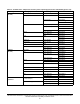


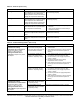
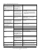
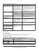
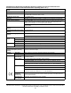

Table Of Contents
- Applications
- North American emissions compliance
- United States
- Canada
- Installation
- Parts included
- Location considerations
- Installing the thermostat controller
- Wiring
- Setup and adjustments
- Overview
- Customizing the home screen
- Touchscreen icons
- User lockout
- Using the USB port
- Loading the firmware
- Backing up the settings
- Restoring the settings
- Choosing the Communication mode (TEC3612 and TEC3613 Models)
- Configuring the network settings for wireless models
- Configuring the thermostat controller
- Installer configuration menu
- Screen reset
- Selecting the unit type
- By default, the thermostat controller is configured for four-pipe fan coil mode. To change to a two-pipe or Pressure-Dependent VAV mode:
- Selecting the heating and cooling device type
- Configuring the supply fan - fan coil only
- Setting the Control mode
- Setting the Fan mode - fan coil only
- Configuring the zone space or equipment size - units configured with floating actuators, multi- speed fans, and variable-speed fans only
- Changeover
- Dehumidification control - fan coil only
- Temperature setpoints
- Configuring occupancy
- Selecting schedule source
- Scheduling (for networked models)
- Setting the local schedule
- Overriding the Occupancy mode
- Enabling optimal start
- Enabling the motion sensor (TEC3x12, TEC3x13 Models)
- PID/PRAC+ automatic control tuning
- Configurable binary inputs
- Aux control
- Commissioning mode
- Configurable analog inputs (AIs)
- Configuring the AIs
- Networked sensors
- Availability of AIs
- Priority for configurable AIs
- Priority for overall sensors data sources
- Available fault diagnostics
- Menus and submenus
- Troubleshooting
- Repair information
- Technical specifications
- TEC3000 Series Networked and Wireless On/Off or Floating Fan Coil and Individual Zone Thermostat Controllers with Dehumidification Capability (Part 1 of 3)

TEC3000 Series Networked and Wireless On/Off or Floating Fan Coil and Individual Zone Thermostat Controllers
with Dehumidification Capability Installation Guide
51
Heating Ineffective The Supply Air Temperature has not
increased above the configured Supply
Air Temperature Alarm Offset while
heating has been active for at least the
Supply Air Temperature Alarm Delay.
Verify that the heating elements on the rooftop
are functioning properly.
Cooling Ineffective The Supply Air Temperature has not
decreased below the configured Supply
Air Temperature Alarm Offset while
cooling has been active for at least the
Supply Air Temperature Alarm Delay.
Verify that the cooling elements on the rooftop are
functioning properly.
Supply Fan Fault The Supply Fan Status configured for
either BI1 or BI2 has not proved within
the configured Fan Alarm Delay.
1. Verify that the Supply Fan is operating when
turned on.
2. Verify that the Supply Fan Status wiring is
connected correctly.
Zone Temperature Too Cold The Zone Temperature has decreased
below the configured Zone Temp Low
Limit.
Verify that the TEC and the RTU heating are
enabled and functioning.
Zone Temperature Too Hot The Zone Temperature has increased
above the configured Zone Temp High
Limit.
Verify that the TEC and the RTU cooling are
enabled and functioning.
Table 16: Troubleshooting details
1
(Part 1 of 3)
Symptom Probable causes Solutions
The controller displays Idle with a
Unit Status of Cooling
Unavailable due to Changeover
despite being above cooling
setpoint, or with a status of
Heating Unavailable due to
Changeover despite being below
the setpoint.
The two-pipe fan coil/VAV system
does not have a changeover
sensor and switch connected, or
the sensor/switch has failed.
1. Check the wiring of the supply temperature
sensor/switch.
2. Verify that the changeover is set up correctly
for the type of sensor attached (sensor or
switch).
The changeover temperature is
sensing a hot supply, but the
controller is requesting cooling.
1. Verify that the supply is not in heating mode. If
it is, nothing can be done from the TEC.
2. Check the wiring of the supply temperature
sensor or switch.
3. Check the placement of the supply
temperature sensor or switch.
4. Verify that the changeover is set up correctly
for the type of sensor attached (sensor or
switch).
Changeover temperature is
sensing a cold supply, but the
controller is requesting heating.
1. Verify that the supply is not in cooling mode. If
it is, nothing can be done from the TEC.
2. Check the wiring of the supply temperature
sensor or switch.
3. Check the placement of supply temperature
sensor or switch.
4. Verify that the changeover is set up correctly
for the type of sensor attached (sensor or
switch).
The controller displays Idle with a
Unit Status of Cooling
Unavailable due to Control Mode
despite being above cooling
setpoint, or with a status of
Heating Unavailable due to
Control Mode despite being below
the setpoint.
The Control Mode is set to
Cooling Mode, but the controller
is requesting heating.
Change the Control Mode to Auto or Heating.
The Control Mode is set to
Heating Mode, but the controller
is requesting cooling.
Change the Control Mode to Auto or Cooling.
Table 15: Fault list (Part 3 of 3)
Faults Probable causes Solutions