
Install Instructions
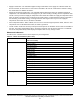
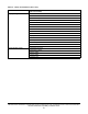
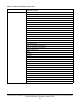


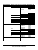


Table Of Contents
- Applications
- North American emissions compliance
- United States
- Canada
- Installation
- Parts included
- Location considerations
- Installing the thermostat controller
- Wiring
- Setup and adjustments
- Overview
- Customizing the home screen
- Touchscreen icons
- User lockout
- Using the USB port
- Loading the firmware
- Backing up the settings
- Restoring the settings
- Choosing the Communication mode (TEC3612 and TEC3613 Models)
- Configuring the network settings for wireless models
- Configuring the thermostat controller
- Installer configuration menu
- Screen reset
- Selecting the unit type
- By default, the thermostat controller is configured for four-pipe fan coil mode. To change to a two-pipe or Pressure-Dependent VAV mode:
- Selecting the heating and cooling device type
- Configuring the supply fan - fan coil only
- Setting the Control mode
- Setting the Fan mode - fan coil only
- Configuring the zone space or equipment size - units configured with floating actuators, multi- speed fans, and variable-speed fans only
- Changeover
- Dehumidification control - fan coil only
- Temperature setpoints
- Configuring occupancy
- Selecting schedule source
- Scheduling (for networked models)
- Setting the local schedule
- Overriding the Occupancy mode
- Enabling optimal start
- Enabling the motion sensor (TEC3x12, TEC3x13 Models)
- PID/PRAC+ automatic control tuning
- Configurable binary inputs
- Aux control
- Commissioning mode
- Configurable analog inputs (AIs)
- Configuring the AIs
- Networked sensors
- Availability of AIs
- Priority for configurable AIs
- Priority for overall sensors data sources
- Available fault diagnostics
- Menus and submenus
- Troubleshooting
- Repair information
- Technical specifications
- TEC3000 Series Networked and Wireless On/Off or Floating Fan Coil and Individual Zone Thermostat Controllers with Dehumidification Capability (Part 1 of 3)

TEC3000 Series Networked and Wireless On/Off or Floating Fan Coil and Individual Zone Thermostat Controllers
with Dehumidification Capability Installation Guide
49
Troubleshooting
Table 15: Fault list (Part 1 of 3)
Faults Probable causes Solutions
Remote Zone Temp Fail The External Zone Temperature
sensor has been disconnected or has
failed.
1. Check the wiring of the sensor.
2. If intentionally disconnected, reset sensors
through the menu.
3. If the problem persists, order replacement
units and return the affected devices to
Johnson Controls under the RMA program.
Supply Temp Fail The External Supply Temperature
sensor has been disconnected or has
failed.
1. Check the wiring of the sensor.
2. If intentionally disconnected, result fault by
entering the menu, enter Control Setup, and
select Inputs to reset the sensors.
3. If the problem persists, order replacement
units and return the affected devices to
Johnson Controls under the RMA program.
Outdoor Temp Fail (For
TEC3x3x Models)
The External Outdoor Air Temperature
sensor has been disconnected or has
failed.
1. Check the wiring of sensor.
2. If intentionally disconnected, reset sensors
through the menu.
3. If problems persist, order replacement units
and return the affected devices to Johnson
Controls under the RMA program.
Internal Sensor Fail An internal sensor has failed on the
TEC.
Order replacement units and return the affected
devices to Johnson Controls under the RMA
program.
Dehum Unavailable Dehumidification is unavailable
because the zone humidity sensor has
failed or the humidity reading is not
reliable.
1. If the source of zone humidity was a BAS,
check the BAS to ensure that it is still online
and is providing the TEC with the humidity
reading. If removal of the BAS mapping was
intentional, reset the sensors through the
menu.
2. (For all models) If the problem persists, order
replacement units and return the affected
devices to Johnson Controls under the RMA
program.
Service Equipment connected to the BI
configured for a Service alarm is
triggering the alarm.
Service the equipment by way of the
manufacturer's recommendation.
Dirty Filter Equipment connected to the BI
configured for a Dirty Filter alarm is
triggering the alarm.
Replace the filter in the equipment as explained in
the manufacturer's instructions.
Calibration Corrupt Factory calibration data is lost or is not
installed.
Order replacement units and return the affected
devices to Johnson Controls under the RMA
program.
Changeover Fail The Supply Temperature Sensor is not
installed, has failed, or has been
disconnected and the TEC can no
longer detect changeover mode to cool
or heat.
Follow the same steps as Supply Temp Fail
alarm.
Zone Temp Unreliable All sources of zone temperature are
unreliable, including the onboard
sensor.
Order replacement units and return the affected
devices to Johnson Controls under the RMA
program.