
Install Instructions
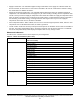
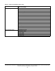
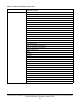


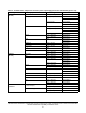


Table Of Contents
- Applications
- North American emissions compliance
- United States
- Canada
- Installation
- Parts included
- Location considerations
- Installing the thermostat controller
- Wiring
- Setup and adjustments
- Overview
- Customizing the home screen
- Touchscreen icons
- User lockout
- Using the USB port
- Loading the firmware
- Backing up the settings
- Restoring the settings
- Choosing the Communication mode (TEC3612 and TEC3613 Models)
- Configuring the network settings for wireless models
- Configuring the thermostat controller
- Installer configuration menu
- Screen reset
- Selecting the unit type
- By default, the thermostat controller is configured for four-pipe fan coil mode. To change to a two-pipe or Pressure-Dependent VAV mode:
- Selecting the heating and cooling device type
- Configuring the supply fan - fan coil only
- Setting the Control mode
- Setting the Fan mode - fan coil only
- Configuring the zone space or equipment size - units configured with floating actuators, multi- speed fans, and variable-speed fans only
- Changeover
- Dehumidification control - fan coil only
- Temperature setpoints
- Configuring occupancy
- Selecting schedule source
- Scheduling (for networked models)
- Setting the local schedule
- Overriding the Occupancy mode
- Enabling optimal start
- Enabling the motion sensor (TEC3x12, TEC3x13 Models)
- PID/PRAC+ automatic control tuning
- Configurable binary inputs
- Aux control
- Commissioning mode
- Configurable analog inputs (AIs)
- Configuring the AIs
- Networked sensors
- Availability of AIs
- Priority for configurable AIs
- Priority for overall sensors data sources
- Available fault diagnostics
- Menus and submenus
- Troubleshooting
- Repair information
- Technical specifications
- TEC3000 Series Networked and Wireless On/Off or Floating Fan Coil and Individual Zone Thermostat Controllers with Dehumidification Capability (Part 1 of 3)

TEC3000 Series Networked and Wireless On/Off or Floating Fan Coil and Individual Zone Thermostat Controllers
with Dehumidification Capability Installation Guide
45
Equipment Setup (Cont) Minimum Command*
Medium Speed On Cmd*
High Speed On Cmd*
Reheat
Reheat Installed
Reheat Min Damper Pos*
Reheat Fan Required*
Changeover
Changeover Mode*
Supply Temp Type*
Changeover Setpoint*
Supply Temp Sensor*
Supply Temp Offset*
Trend EFF-ZNT
EFF-SETPOINT
EFF-ZNH
B1 Status
B2 Status
EFF-OAT
EFF-SAT
FANSPD-S
CLG1-C
CLG2-C
HTG1-C
HTG2-C
OAD-O
HTG-O
CLG-O
System Status Occupancy Source
Unit Status
Supply Air Temperature
Changeover State
Zone Temp Source
Control Status Cooling % Command
Heating % Command
Reheat % Command
Cool Stage 1
Heat Stage 1
Reheat Stage 1
Fan % Command
Fan
Table 13: Menus and submenus (Part 5 of 6)
Level 1 Level 2
(LCD screen name)