
Install Instructions
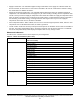
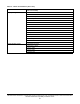
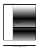


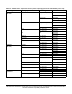


Table Of Contents
- Applications
- North American emissions compliance
- United States
- Canada
- Installation
- Parts included
- Location considerations
- Installing the thermostat controller
- Wiring
- Setup and adjustments
- Overview
- Customizing the home screen
- Touchscreen icons
- User lockout
- Using the USB port
- Loading the firmware
- Backing up the settings
- Restoring the settings
- Choosing the Communication mode (TEC3612 and TEC3613 Models)
- Configuring the network settings for wireless models
- Configuring the thermostat controller
- Installer configuration menu
- Screen reset
- Selecting the unit type
- By default, the thermostat controller is configured for four-pipe fan coil mode. To change to a two-pipe or Pressure-Dependent VAV mode:
- Selecting the heating and cooling device type
- Configuring the supply fan - fan coil only
- Setting the Control mode
- Setting the Fan mode - fan coil only
- Configuring the zone space or equipment size - units configured with floating actuators, multi- speed fans, and variable-speed fans only
- Changeover
- Dehumidification control - fan coil only
- Temperature setpoints
- Configuring occupancy
- Selecting schedule source
- Scheduling (for networked models)
- Setting the local schedule
- Overriding the Occupancy mode
- Enabling optimal start
- Enabling the motion sensor (TEC3x12, TEC3x13 Models)
- PID/PRAC+ automatic control tuning
- Configurable binary inputs
- Aux control
- Commissioning mode
- Configurable analog inputs (AIs)
- Configuring the AIs
- Networked sensors
- Availability of AIs
- Priority for configurable AIs
- Priority for overall sensors data sources
- Available fault diagnostics
- Menus and submenus
- Troubleshooting
- Repair information
- Technical specifications
- TEC3000 Series Networked and Wireless On/Off or Floating Fan Coil and Individual Zone Thermostat Controllers with Dehumidification Capability (Part 1 of 3)

TEC3000 Series Networked and Wireless On/Off or Floating Fan Coil and Individual Zone Thermostat Controllers
with Dehumidification Capability Installation Guide
41
• Supply Fan Runtime—The TEC3000 supports setting runtime limits on the supply fan command. When the
limit is exceeded, an alarm turns on. This feature is intended to be used as a maintenance reminder. Setting
the runtime limit to 0 disables this feature.
• Supply Air Temperature Diagnostics—The TEC3000 supports diagnostics when you installed a Supply Air
Temperature. The TEC3000 monitors the supply air. If you call for cooling or heating and the temperature does
not fall or rise by at least the supply air temperature alarm offset value within the supply air temperature alarm
delay, an alarm is generated. If the monitoring occurs while cooling, a cooling ineffective alarm is generated. If
the monitoring occurs while heating, a heating ineffective alarm is generated. If you set the supply air
temperature offset value set to 0, this alarm is disabled.
• Zone Temperature Alarm—When enabled, the user can set a low and high temperature alarm; and if the zone
temperature rises or falls below those limits, an alarm is generated.
• Trends—Built-in trends exist for many of the inputs and outputs for the TEC3000. These trends are viewable at
the TEC. The analog graph displays data in 15-minute increments over the previous 24 hours or a table with
the last 25 data points. Binary trends display 25 samples taken at every change of state.
Menus and submenus
In Table 13, the * indicates that the menus depend on your configuration.
Table 13: Menus and submenus (Part 1 of 6)
Level 1 Level 2
(LCD screen name)
Setpoints Occupied Cooling
Occupied Heating
Unoccupied Cooling
Unoccupied Heating
Standby Cooling
Standby Heating
Dehumidification*
Occ Setpoint Select
Heat Cool Setpoint Mode
Max Heating Setpoint*
Min Heating Setpoint*
Max Cooling Setpoint*
Min Cooling Setpoint*
Max Setpoint*
Min Setpoint*
Scheduling Schedule Options
Set Schedule
Optimal Start Enable
Temp Occ Duration
Motion Sensor Timeout
Manual Occupancy Mode
Schedule Source