
Install Instructions
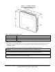
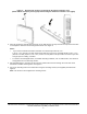
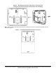

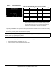
Table Of Contents
- Applications
- North American emissions compliance
- United States
- Canada
- Installation
- Parts included
- Location considerations
- Installing the thermostat controller
- Wiring
- Setup and adjustments
- Overview
- Customizing the home screen
- Touchscreen icons
- User lockout
- Using the USB port
- Loading the firmware
- Backing up the settings
- Restoring the settings
- Choosing the Communication mode (TEC3612 and TEC3613 Models)
- Configuring the network settings for wireless models
- Configuring the thermostat controller
- Installer configuration menu
- Screen reset
- Selecting the unit type
- By default, the thermostat controller is configured for four-pipe fan coil mode. To change to a two-pipe or Pressure-Dependent VAV mode:
- Selecting the heating and cooling device type
- Configuring the supply fan - fan coil only
- Setting the Control mode
- Setting the Fan mode - fan coil only
- Configuring the zone space or equipment size - units configured with floating actuators, multi- speed fans, and variable-speed fans only
- Changeover
- Dehumidification control - fan coil only
- Temperature setpoints
- Configuring occupancy
- Selecting schedule source
- Scheduling (for networked models)
- Setting the local schedule
- Overriding the Occupancy mode
- Enabling optimal start
- Enabling the motion sensor (TEC3x12, TEC3x13 Models)
- PID/PRAC+ automatic control tuning
- Configurable binary inputs
- Aux control
- Commissioning mode
- Configurable analog inputs (AIs)
- Configuring the AIs
- Networked sensors
- Availability of AIs
- Priority for configurable AIs
- Priority for overall sensors data sources
- Available fault diagnostics
- Menus and submenus
- Troubleshooting
- Repair information
- Technical specifications
- TEC3000 Series Networked and Wireless On/Off or Floating Fan Coil and Individual Zone Thermostat Controllers with Dehumidification Capability (Part 1 of 3)

TEC3000 Series Networked and Wireless On/Off or Floating Fan Coil and Individual Zone Thermostat Controllers
with Dehumidification Capability Installation Guide
4
Installing the thermostat controller
1. Use a 1/16 in. (1.5 mm) Allen wrench or Johnson Controls® T-4000-119 Allen-Head Adjustment Tool (order
separately) to remove the security screw if it is installed on the top of the thermostat controller cover as
illustrated in Figure 2.
2. Pull the top edge of the cover and open the thermostat controller as illustrated in Figure 2.
Table 2: Thermostat controller features
Callout Description
1 Security Screw
2 Display
3 USB Port
IMPORTANT: The cover is not secured on the bottom. Be careful not to drop the cover.
IMPORTANT: If you install more than one thermostat controller, keep track of which cover attaches to which
base. The controller version and the base version must match to ensure proper operation.
IMPORTANT: Use proper Electrostatic Discharge (ESD) precautions during installation and servicing to avoid
damage to the electronic circuits of the thermostat controller.
Figure 1: Thermostat controller
shown without occupancy sensor,
dimensions, in. (mm)