
Install Instructions
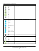
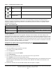


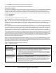
Table Of Contents
- Applications
- North American emissions compliance
- United States
- Canada
- Installation
- Parts included
- Location considerations
- Installing the thermostat controller
- Wiring
- Setup and adjustments
- Overview
- Customizing the home screen
- Touchscreen icons
- User lockout
- Using the USB port
- Loading the firmware
- Backing up the settings
- Restoring the settings
- Choosing the Communication mode (TEC3612 and TEC3613 Models)
- Configuring the network settings for wireless models
- Configuring the thermostat controller
- Installer configuration menu
- Screen reset
- Selecting the unit type
- By default, the thermostat controller is configured for four-pipe fan coil mode. To change to a two-pipe or Pressure-Dependent VAV mode:
- Selecting the heating and cooling device type
- Configuring the supply fan - fan coil only
- Setting the Control mode
- Setting the Fan mode - fan coil only
- Configuring the zone space or equipment size - units configured with floating actuators, multi- speed fans, and variable-speed fans only
- Changeover
- Dehumidification control - fan coil only
- Temperature setpoints
- Configuring occupancy
- Selecting schedule source
- Scheduling (for networked models)
- Setting the local schedule
- Overriding the Occupancy mode
- Enabling optimal start
- Enabling the motion sensor (TEC3x12, TEC3x13 Models)
- PID/PRAC+ automatic control tuning
- Configurable binary inputs
- Aux control
- Commissioning mode
- Configurable analog inputs (AIs)
- Configuring the AIs
- Networked sensors
- Availability of AIs
- Priority for configurable AIs
- Priority for overall sensors data sources
- Available fault diagnostics
- Menus and submenus
- Troubleshooting
- Repair information
- Technical specifications
- TEC3000 Series Networked and Wireless On/Off or Floating Fan Coil and Individual Zone Thermostat Controllers with Dehumidification Capability (Part 1 of 3)

TEC3000 Series Networked and Wireless On/Off or Floating Fan Coil and Individual Zone Thermostat Controllers
with Dehumidification Capability Installation Guide
22
User lockout
You can select from three different levels of access at the local display to manage functionality through the
supervisory controller. This lockout is independent of any display or passcode settings. The existing temporary
occupancy capability is unaffected by this feature. User lockout hides the icons that are not operable. Table 6
describes the lockout levels.
Using the USB port
You can quickly and easily load firmware upgrades, back up the current settings, and restore settings to the
TEC3000 through the USB port with a USB drive. The TEC3000 can recognize eight configuration files or firmware
package files. The USB drive format must be FAT or FAT32. The drive cannot be NTFS format or USB 3.0. If you
upgrade the firmware or copy configuration files, you need the passcode if one is set up. Do not remove the USB
drive until the firmware upgrade is complete. The TEC3000 may restart and go offline to the NAE after a firmware
upgrade. The upgrade takes approximately three minutes.
Configurations are copied, except for the Communication mode. See Choosing the Communication mode
(TEC3612 and TEC3613 Models) to configure the networked devices.
Loading the firmware
1. Ensure that the TEC screen is on.
2. Insert the USB drive into the right side of the TEC.
See Figure 1 for the USB port location.
3. Press the Menu icon.
4. Scroll down the menu and press Update.
5. Press Load Firmware.
6. Select the correct firmware version. The correct file name has the .pkg extension.
7. Press Confirm if you have the correct firmware version.
The firmware is loaded from the USB drive into the TEC3000 operating system. The TEC3000 locates the new
firmware only if the new firmware is on the root drive of the USB drive. See Table 15 if the firmware is not
loaded correctly.
8. Remove the USB drive from the TEC3000 controller when the update is complete.
Delete
Deletes the scheduled event.
Clear
Clears the password entry on the keypad screen.
Exclamation point
Indicates that an error has occurred.
Table 6: User lockout levels
Lockout level Capability
State 0
Allows full access to Home Screen Display Adjustments and icons (default).
State 1
Hides the Menu icon.
State 2
Only allows the screen to trigger temporary occupancy. Menu, Unit Power, the Up
and Down arrows, and Run/Hold are hidden.
Table 5: Touchscreen icons (Part 5 of 5)
Icon Icon name Description