
Install Instructions
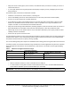
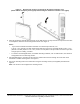
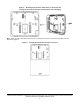

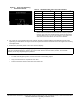
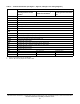
Table Of Contents
- Applications
- North American emissions compliance
- United States
- Canada
- Installation
- Parts included
- Location considerations
- Installing the thermostat controller
- Wiring
- Setup and adjustments
- Overview
- Customizing the home screen
- Touchscreen icons
- User lockout
- Using the USB port
- Loading the firmware
- Backing up the settings
- Restoring the settings
- Choosing the Communication mode (TEC3612 and TEC3613 Models)
- Configuring the network settings for wireless models
- Configuring the thermostat controller
- Installer configuration menu
- Screen reset
- Selecting the unit type
- By default, the thermostat controller is configured for four-pipe fan coil mode. To change to a two-pipe or Pressure-Dependent VAV mode:
- Selecting the heating and cooling device type
- Configuring the supply fan - fan coil only
- Setting the Control mode
- Setting the Fan mode - fan coil only
- Configuring the zone space or equipment size - units configured with floating actuators, multi- speed fans, and variable-speed fans only
- Changeover
- Dehumidification control - fan coil only
- Temperature setpoints
- Configuring occupancy
- Selecting schedule source
- Scheduling (for networked models)
- Setting the local schedule
- Overriding the Occupancy mode
- Enabling optimal start
- Enabling the motion sensor (TEC3x12, TEC3x13 Models)
- PID/PRAC+ automatic control tuning
- Configurable binary inputs
- Aux control
- Commissioning mode
- Configurable analog inputs (AIs)
- Configuring the AIs
- Networked sensors
- Availability of AIs
- Priority for configurable AIs
- Priority for overall sensors data sources
- Available fault diagnostics
- Menus and submenus
- Troubleshooting
- Repair information
- Technical specifications
- TEC3000 Series Networked and Wireless On/Off or Floating Fan Coil and Individual Zone Thermostat Controllers with Dehumidification Capability (Part 1 of 3)

TEC3000 Series Networked and Wireless On/Off or Floating Fan Coil and Individual Zone Thermostat Controllers
with Dehumidification Capability Installation Guide
10
Table 4: Terminal identification (See Figure 7, Figure 8, and Figure 9 for wiring diagrams)
Terminal label Function
TEC3012, TEC3013
Floating FC/VAV and On/
Off FC
1
TEC3312, TEC3313 Floating
FC/VAV and On/Off FC
1
TEC3612, TEC3613
Floating FC/VAV and On/Off
FC
1
24 V 24 VAC hot from transformer
FAN H Fan high
FAN M Fan medium
FAN L Fan on (single-speed, variable-speed), Fan low (multi-speed)
AUX Auxiliary binary output
AUX Auxiliary power
COM
2
24 VAC common from transformer
COM
2
24 VAC common from transformer
CLG O Cool open (Floating), Cooling NC (On/Off), Triac
CLG C Cool close (Floating), Cooling NO (On/Off), Triac
HTG O Heat open (Floating), Heating NC (On/Off), Triac
HTG C Heat close (Floating), Heating NO (On/Off), Triac
RSEN Configurable analog input 1
COS Configurable analog input 2/Changeover binary switch input
VSF Variable speed fan command (configurable 0 to 10 V range)
BI-2 Configurable binary input 2
BI-1 Configurable binary input 1
NET+ N/A Not connected Field bus+/N2+
NET- N/A Not connected Field bus-/N2-
NET COM N/A Not connected Isolated common for field bus
1. There is no support for an On and Off VAV.
2. COM on TB1 must be jumpered to COM on TB2.