TEC3000 Series Networked and Wireless On/Off or Floating Fan Coil and Individual Zone Thermostat Controllers with Code No. LIT-12013161 Dehumidification Capability Issued May 2019 Installation Guide TEC3012-1x-xxx, TEC3013-1x-xxx,TEC3310-1x-xxx, TEC3313-1x-xxx, TEC3612-1x-xxx, TEC3613-1x-xxx Refer to the QuickLIT website for the most up-to-date version of this document.
IMPORTANT: The TEC3000 Series Thermostat Controller is intended to provide an input to equipment under normal operating conditions. Where failure or malfunction of the thermostat controller could lead to personal injury or property damage to the controlled equipment or other property, additional precautions must be designed into the control system.
• Away from steam or water pipes, warm air stacks, unconditioned areas (not heated or cooled), or sources of electrical interference • In a clear path between the integrated passive infrared (PIR) occupancy sensor (if equipped) and the space being monitored For wireless models, also locate the thermostat controller: • Outside of a recessed area, metal enclosure, or shelving unit • On the same building level as the other wireless devices on the same personal area network (PAN) • At least 2 in.
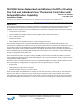
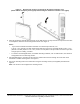
Figure 1: Thermostat controller shown without occupancy sensor, dimensions, in. (mm) Table 2: Thermostat controller features Callout Description 1 Security Screw 2 Display 3 USB Port Installing the thermostat controller 1. Use a 1/16 in. (1.5 mm) Allen wrench or Johnson Controls® T-4000-119 Allen-Head Adjustment Tool (order separately) to remove the security screw if it is installed on the top of the thermostat controller cover as illustrated in Figure 2. 2.
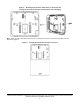
Figure 2: Removing the security screw from the thermostat controller cover (shown without occupancy sensor) (left) and removing the thermostat controller cover (right) 3. Align the thermostat controller mounting base on the wall with the security screw on the top and use the base as a template to mark the two mounting hole locations. See Figure 3. Notes: • If you need to install the thermostat controller on an electrical junction box, use 2-1/2 in. x 4 in.
Figure 3: Mounting hole locations, dimensions, in. (mm) (left) and securing the thermostat controller mounting base to the wall (right) Note: When the unit is mounted on the wall, you can hang the front cover on the end of the back cover as illustrated in Figure 4.
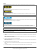
Wiring When an existing thermostat controller is replaced, remove and label the wires to identify the terminal functions. Risk of Electric Shock. Disconnect the power supply before making electrical connections to avoid electric shock. Risque de décharge électrique. Débrancher l'alimentation avant de réaliser tout raccordement électrique afin d'éviter tout risque de décharge électrique. Risk of Property Damage. Do not apply power to the system before checking all wiring connections.
The bus EOL termination switch allows you to designate the thermostat controller as the end of the Field Controller (FC) Bus and N2 Bus. The default position is OFF. If the thermostat controller is at the end of a daisy chain of devices on the FC Bus and N2 Bus, set the EOL switch to the ON position. See Figure 5. Figure 5: EOL switch position (left) and installing the thermostat controller cover (right) 5. Reattach the thermostat controller cover to the mounting base (bottom side first).
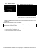
Figure 6: Error code indicating mismatched boards Table 3: TEC3000 model names and code numbers Name Code number1 Name Code number1 TEC3012 22 TEC3323 07 TEC3013 23 TEC3330 08 TEC3022 26 TEC3331 09 TEC3023 27 TEC3612 0C TEC3030 28 TEC3613 0D TEC3031 29 TEC3622 10 TEC3312 02 TEC3623 11 TEC3313 03 TEC3630 12 TEC3322 06 TEC3631 13 1. The two-character code number is listed within the error code to indicate that the CPU board and base board do not belong together.
Table 4: Terminal identification (See Figure 7, Figure 8, and Figure 9 for wiring diagrams) Terminal label Function TEC3012, TEC3013 Floating FC/VAV and On/ Off FC1 TEC3312, TEC3313 Floating FC/VAV and On/Off FC1 24 V 24 VAC hot from transformer FAN H Fan high FAN M Fan medium FAN L Fan on (single-speed, variable-speed), Fan low (multi-speed) AUX Auxiliary binary output AUX TEC3612, TEC3613 Floating FC/VAV and On/Off FC1 Auxiliary power 2 24 VAC common from transformer COM2 24 VAC common f
Figure 7: On/off wiring diagram (See Table 4 for terminal identification) TEC3000 Series Networked and Wireless On/Off or Floating Fan Coil and Individual Zone Thermostat Controllers with Dehumidification Capability Installation Guide 11
Figure 8: Low side switched floating wiring diagram (See Table 4 for terminal identification) TEC3000 Series Networked and Wireless On/Off or Floating Fan Coil and Individual Zone Thermostat Controllers with Dehumidification Capability Installation Guide 12
Figure 9: High side switched floating wiring diagram (See Table 4 for terminal identification) TEC3000 Series Networked and Wireless On/Off or Floating Fan Coil and Individual Zone Thermostat Controllers with Dehumidification Capability Installation Guide 13
Figure 10: Floating control (pressure-dependent VAV) Figure 11: Floating control (pressure-dependent VAV with changeover sensor/switch) Figure 12: Floating control (pressure-dependent VAV with changeover sensor/switch and reheat) TEC3000 Series Networked and Wireless On/Off or Floating Fan Coil and Individual Zone Thermostat Controllers with Dehumidification Capability Installation Guide 14
Figure 13: Floating control two-pipe heating and cooling hydronic valve control fan coil application Figure 14: Floating control two-pipe heating and cooling hydronic valve control with changeover fan coil application Figure 15: Floating control (on/off two-pipe and four-pipe fan coil applications) Triac Switch Triac Switch Triac Switch 24V COM Heating Valve Two-Pipe Applications COM Cooling Valve Four-Pipe Applications FIG:model_1_onoff 24V TEC3000 Series Networked and Wireless On/Off or Floati
Figure 16: Floating control (floating two-pipe and four-pipe fan coil applications) Triac Switch Triac Switch HTG O HTG C 24V Triac Switches COM CLG O CLG C HTG O HTG C 24V COM Heating/Cooling Valve Heating Valve Two-Pipe Applications Four-Pipe Applications FIG:model_1_floating Cooling Valve Figure 17: (Floating control two-pipe heating and cooling hydronic valve control fan coil application Figure 18: Floating control two-pipe heating and cooling hydronic valve control with changeover fa
Figure 20: Binary input wiring Dry Contact BI1 Bi2 FIG:Binary Input Wiring Dry Contact Setup and adjustments IMPORTANT: Table 13 provides a full list of TEC3000 menu settings. The upcoming sections include step-bystep instructions on how to access and adjust the more commonly used menus. Overview Figure 21 shows the thermostat controller home screen in both the light and dark themes. You can customize it to show or hide various elements from the occupant.
Figure 22: Thermostat controller home screen in cooling mode (left) and heating mode (right) Customizing the home screen Customizing the Home screen settings include: • Brightness • Units • Time Zone • Date • Enable Backlight • Time • Time Format • Date Format • Date/Time You can also show or hide these items on the Home screen: • Fan Button • Off Button • Alarms • Temperature • Hold Button • Occupancy Status • Humidity • Setpoint • Unit Status To customize the Home scre
Table 5: Touchscreen icons (Part 2 of 5) Icon Icon name Description Unit Power On Powers the thermostat controller on or off. Notes: • This icon disables all equipment control but does not physically power down the unit. • On the modern home screen, if the Unit Power icon is in standby mode, the temperature and humidity are also displayed in standby mode to indicate that control off or standby mode is active. Standby Humidity On Indicates the humidity reading.
Table 5: Touchscreen icons (Part 3 of 5) Icon Icon name Description Cooling Hold Indicates that cooling hold mode is enabled. Hold mode is disabled by pressing the button. Heating Hold Indicates that heating hold mode is enabled. Hold mode is disabled by pressing the button. Cooling Setpoint Heating Setpoint Setpoint Temperature Displays the current cooling setpoint. Indicates that Hold mode is disabled. To enable Hold mode, press the button. Displays the current heating setpoint.
Table 5: Touchscreen icons (Part 4 of 5) Icon Icon name Description Fan Overrides for Multi-speed Fans Adjusts the fan override between Low, Medium, High, Auto, and Quiet for multi-speed fans. Low Medium High Auto Quiet Occupancy Status Adjusts the occupancy between Unoccupied, Occupied, Temporarily Occupied, Standby, Occupancy Override, Unoccupancy Override. Unoccupied Occupied Temporarily Occupied Standby Override - Occupied Override - Unnoccupied Moves the display to the previous screen.
Table 5: Touchscreen icons (Part 5 of 5) Icon Icon name Description Deletes the scheduled event. Delete Clears the password entry on the keypad screen. Clear Indicates that an error has occurred. Exclamation point User lockout You can select from three different levels of access at the local display to manage functionality through the supervisory controller. This lockout is independent of any display or passcode settings. The existing temporary occupancy capability is unaffected by this feature.
The TEC3000 firmware update is complete when the TEC3000 restarts and returns to the home screen. Backing up the settings Note: When you back up the settings, the network settings are not backed up or restored. 1. Ensure that the TEC screen is on. 2. Insert the USB drive into the right side of the TEC. See Figure 1 for the USB port location. 3. Press the Menu icon. 4. Scroll down the menu and press Update. 5. Press Backup. A message appears stating that the file is saved locally and on a USB drive. 6.
9. Press BACnet Instance ID. 10. Enter the unique BACnet® instance ID using the keypad. This value should be different to the other controllers on the site. 11. Press Save. 12. Press the back arrow to return to the previous screen. 13. Press BACnet Address. 14. Enter the BACnet MS/TP address through the keypad. 15. Press Save. 16. After selecting N2 in Step 6, press Save. 17. Press the back arrow to return to the previous screen. 18. Press N2 Address. 19. Enter the N2 address through the keypad. 20.
Configuring the thermostat controller Use the Menu icon on the home screen to access and change the basic operating parameters of the thermostat controller. During normal operation, press the Menu icon once to access the following parameters: • Fault Status • Display Settings • Status • Setpoints • Setup • Update • Schedule • Trend Installer configuration menu The thermostat controller comes from the factory with default settings for all configuration parameters.
4. Press General. 5. Press Htg/Clg Device Type and select On-Off or Floating. Changing this option reboots the controller in order to apply the change. 6. Press Save and the back arrow to return to the previous screen. When in Floating mode, the Actuator Stroke Time must also be set to match the equipment. To set the actuator stroke time: 1. Press the Menu icon. 2. Press Setup. 3. Press Equipment Setup. 4. Press General. 5. Press Actuator Stroke Time and adjust accordingly. 6.
To configure the variable speed parameters: 1. Press the Menu icon. 2. Press Setup. 3. Press Equipment Setup. 4. Press Supply Fan. 5. Press Start Voltage and adjust accordingly. 6. Press Full Speed Voltage and adjust accordingly. 7. Press Minimum Command and adjust accordingly. 8. Press Save and the back arrow to return to the previous screen.
The following Fan Override options are provided for multi-speed fans: • Low—Fan is continuously on low • Medium—Fan is continuously on medium • High—Fan is continuously on high • Auto—Follows the behavior set as Fan Mode • Quiet—Follows the behavior set as Fan Mode, but prevents the fan from ever going above minimum speed To set the Fan Mode: 1. Press the Menu icon. 2. Press Setup. 3. Press General Control Setup. 4. Press Fan Mode and select On, Auto, or Smart. 5.
5. Press Changeover Mode and select Auto. 6. Press Supply Temp Type and select Analog Sensor, Cooling N.C., or Heating N.C. 7. If using an Analog Supply Temp Sensor, press Supply Temp Type and adjust accordingly. 8. Press Save and the back arrow to return to the previous screen. Additionally, the thermostat controller supports manual changeover. To configure manual changeover: 1. Press the Menu icon. 2. Press Setup. 3. Press Equipment Setup. 4. Press Changeover. 5.
4. Press Save and the back arrow to return to the previous screen. This point is also exposed to the BAS through the point DEHUM-SP. Temperature setpoints The thermostat controller provides a flexible setpoint configuration to give power to the building owner while being easy to use by the occupant. In addition to a simple up/down offset adjustment on the home screen for the occupant, the TEC features six temperature setpoints.
Table 7: Setpoint operation Mode of setpoint operation Details Occ Setpoint Select = Setpoint Offset and Heat Cool Setpoint Mode = Common Setpoint In this mode, the TEC has one setpoint, Common Setpoint, for heating and cooling. There is also a common Setpoint Offset (warmer/cooler adjust) that is only applied to Common Setpoint. Otherwise, this setting works the same as when Occ Setpoint Select = Setpoint Offset and Heat Cool Setpoint Mode = Individual Setpoints.
Enumerations may not match TEC3000 Series Networked and Wireless On/Off or Floating Fan Coil and Individual Zone Thermostat Controllers with Dehumidification Capability Installation Instructions (LIT-12013161) and TEC3000 Series Field-Selectable BACnet MS/TP or N2 Networked Thermostat Controllers Technical Bulletin (LIT12011956) for NAE releases prior to 7.x.
If the OCC-CONFIG is set to Schedule, the internal schedule commands the LOCAL-OCC object, which sets the Occupancy Schedule command. Note: If you do not have a schedule in the Schedule object and you have the OCC-CONFIG set to Schedule, you can control the unit with the LOCAL-OCC object externally; however, we do not recommend this method. See Table 9 for scheduling information.
5. Select the days to which the schedule should apply. Note that if events are already set for the selected days, they appear in the corresponding event box. If any events conflict between selected days, an asterisk appears in the event box. See Figure 23. 6. Select the Occupancy Status icon for the event. See Figure 24. IMPORTANT: Internally, the TEC3000 uses a BACnet schedule where daily schedules are independent of the previous and next days.
Note: If you do not select Save at this point, the event is not saved and you must repeat the event selection sequence. Figure 26: Saving the event 10. Select Event 2. See Figure 27. The screen resets to the Event 2 Set Schedule screen. The days are preselected to match Event 1. 11. Select the Occupancy Status button for Event 2. Figure 27: Selecting event 2 (left) and setting the occupancy status (right) 12. Select the Time Set button. 13. Set the time for Event 2 and press Save. 14.
Enabling optimal start The TEC supports an advanced optimal start algorithm. The algorithm works in conjunction with a local schedule to pre-heat or pre-cool the zone before scheduled occupancy periods begin, in order to bring the zone to the desired occupied setpoint when the scheduled occupancy period begins. Occupant comfort is ensured while automatically minimizing energy usage.
2. Press Setup. 3. Press General Control Setup. 4. Press Tuning. 5. Press Temp Control Setup. 6. Select Manual PID Tuning (or any option listed in Table 10). 7. Press Save and the back arrow to return to the previous screen. As a result of disabling PRAC+ Automatic Tuning, you have access to different types of manual tuning that allows modifications of tuning parameters listed under Control Setup > General in Table 13.
The Open Door option works in conjunction with a motion sensor, either built into the TEC or connected to another BI configured for Motion NO/NC mode. When the door is open, motion detected by the sensor is ignored. Note that opening the door does not stop an Occupied period started by the motion sensor prior to opening the door. Table 11 provides the polarity of the inputs.
Commissioning mode The thermostat controller has a built-in commissioning mode, which is designed to allow you to quickly test equipment wiring and functionality. Commissioning mode temporarily disables the control logic, and allows you to manually command any individual output.
b. Press Menu > Setup > Input Setup > AI1 Offset and select the temperature offset as needed for the sensor connected to RSEN. The options are -5°F to 5°F or -2.8°C to 2.8°C. • If the selected sensor is a Relative Humidity, Carbon Dioxide, or Damper feedback sensor, the Input Setup is automatically set to 0-10 VDC. Press Menu > Setup > Input Setup > AI1 Offset and select the offset needed for the sensor connected to RSEN.
• Supply Fan Runtime—The TEC3000 supports setting runtime limits on the supply fan command. When the limit is exceeded, an alarm turns on. This feature is intended to be used as a maintenance reminder. Setting the runtime limit to 0 disables this feature. • Supply Air Temperature Diagnostics—The TEC3000 supports diagnostics when you installed a Supply Air Temperature. The TEC3000 monitors the supply air.
Table 13: Menus and submenus (Part 2 of 6) Level 1 Level 2 (LCD screen name) Display Settings Passcode Enabled Passcode* Brightness Setting Enable Backlight Timeout Units Time Time Zone Set Time Format Date Set Date Format Language Show Fan Button on Home Show Temp on Home Show Humidity on Home Show Off Button on Home Show Hold Button Display Settings (Cont) Show Setpoint on Home Show Alarms on Home Show Occ Status Show Unit Status Show Date/Time TEC3000 Series Networked and Wireless On/Off or Floatin
Table 13: Menus and submenus (Part 3 of 6) Level 1 Level 2 (LCD screen name) Setup General Control Setup Control Mode Unit Enable Fan Mode* Max Setpoint Offset Fan On Delay* Fan Off Delay* Frost Protection Dehum Enable* (for TEC3x1x and TEC3x2x models) Aux Mode Load Shed Rate Limit Load Shed Adjust Fan Alarm Delay Fan Alarm Action* Fan Alarm Reset* Fan Runtime Limit Fan Runtime Reset* Supply Air Temperature Alarm Offset Supply Air Temperature Alarm Delay* Unocc Low Speed Fan Inputs BI1 Config BI2 Config
Table 13: Menus and submenus (Part 4 of 6) Level 1 Level 2 (LCD screen name) Setup (Cont) Deadband* Auto Economizer Tuning Heat Prop Band* Heat Integral Time* Heat Process Range* Heat Saturation Time* Heat Time Constant* Heat Process Dead Time* Heat Period* Cool Prop Band* Cool Integral Time* Cool Process Range* Cool Saturation Time* Cool Time Constant* Cool Process Dead Time* Cool Period* Equipment Size Network Setup FC Comm Mode BACnet Instance ID* N2 Address* (for networked models) BACnet Address* MST
Table 13: Menus and submenus (Part 5 of 6) Level 1 Level 2 (LCD screen name) Equipment Setup (Cont) Minimum Command* Medium Speed On Cmd* High Speed On Cmd* Reheat Reheat Installed Reheat Min Damper Pos* Reheat Fan Required* Changeover Changeover Mode* Supply Temp Type* Changeover Setpoint* Supply Temp Sensor* Supply Temp Offset* Trend EFF-ZNT EFF-SETPOINT EFF-ZNH B1 Status B2 Status EFF-OAT EFF-SAT FANSPD-S CLG1-C CLG2-C HTG1-C HTG2-C OAD-O HTG-O CLG-O System Status Occupancy Source Unit Status Supp
Table 13: Menus and submenus (Part 6 of 6) Level 1 Level 2 (LCD screen name) Controller Info Model Name Software Version Unit Name Device Name Device Description Commissioning Supply Air Temperature Heat Command Cool Command Supply Fan Aux Update View Version Load Firmware Restore* Backup* Network Status (For Wireless Models) Radio Code Version Radio PAN ID Active Channel Signal Strength Connection Status Network State IEEE Address Short Address TEC3000 Series Networked and Wireless On/Off or Floa
Table 14: TE-6300 Series Temperature Sensors (order separately) (for wireless TEC Models) (Part 1 of 2) Sensor type Mounting style Probe length Product code number Nickel (1k ohm) Adjustable1 8 in. (203 mm) TE-6311A-1 Averaging 8 ft (2.4 m) TE-6315M-1 TE-6315V-21 17 ft (5.2 m) TE-6316M-1 TE-6316V-21 Duct 4 in. (102 mm) TE-631GM-1 8 in. (203 mm) TE-6311M-1 TE-6311P-1 Flange Flush 18 in. (457 mm) TE-631JM-1 4 in. (102 mm) TE-631GV-2 8 in.
Table 14: TE-6300 Series Temperature Sensors (order separately) (for wireless TEC Models) (Part 2 of 2) Sensor type Mounting style Probe length Product code number Thermistor (2.2k ohm) Adjustable 8 in. (203 mm) TE-6341A-1 Duct 8 in. (203 mm) TE-6341P-1 Flange 4 in. (102 mm) TE-634GV-2 Thermistor (10k ohm) Type II 8 in. (203 mm) TE-6341V-2 Outside air 3 in. (76 mm) TE-6343P-1 Wall2 N/A TE-6344P-1 Well 8 in. (203 mm) TE-6342M-1 6 in. (152 mm) TE-634AM-2 Adjustable 8 in.
Troubleshooting Table 15: Fault list (Part 1 of 3) Faults Probable causes Solutions Remote Zone Temp Fail The External Zone Temperature sensor has been disconnected or has failed. 1. Check the wiring of the sensor. 2. If intentionally disconnected, reset sensors through the menu. 3. If the problem persists, order replacement units and return the affected devices to Johnson Controls under the RMA program. Supply Temp Fail The External Supply Temperature sensor has been disconnected or has failed. 1.
Table 15: Fault list (Part 2 of 3) Faults Probable causes Solutions Open Window The switch connected to the BI configured for Open Window is sensing that the window is opened, and control has shut down. 1. Close the window to resume control. 2. Check sensor functionality with an ohmmeter, and verify the wiring to the TEC. 3. Order replacement units and return the affected devices to Johnson Controls under the RMA program.
Table 15: Fault list (Part 3 of 3) Faults Probable causes Solutions Heating Ineffective The Supply Air Temperature has not increased above the configured Supply Air Temperature Alarm Offset while heating has been active for at least the Supply Air Temperature Alarm Delay. Verify that the heating elements on the rooftop are functioning properly.
Table 16: Troubleshooting details1 (Part 2 of 3) Symptom Probable causes Solutions The staged equipment shuts off above the cooling setpoint or below the heating setpoint when the PID is running on the TEC. If the unit is in On/Off Control mode, this does not apply. The PID control algorithm minimizes overshoot and energy usage for the particular equipment and zone, and may cycle the equipment prior to reaching setpoint. Expected behavior.
Table 16: Troubleshooting details1 (Part 3 of 3) Symptom Probable causes Solutions Partial Restore Complete is displayed when trying to restore settings from a backup file. Not all of the items in the backup file have been restored. This error can be caused by a value being out of the minimum or maximum range in the backup file. It may also occur if there are inconsistencies in the reliability of a setting in the backup file and on the TEC device. 1.
TEC3000 Series Networked and Wireless On/Off or Floating Fan Coil and Individual Zone Thermostat Controllers with Dehumidification Capability (Part 2 of 3 ) Auxiliary output rating/triac output 19 to 30 VAC, 1.0 A maximum, 15 mA minimum, 3.0 A in-rush Binary inputs Dry contact across terminal COM to terminals BI1, BI2, or COS Analog inputs Nickel, platinum, A99B, 2.
TEC3000 Series Networked and Wireless On/Off or Floating Fan Coil and Individual Zone Thermostat Controllers with Dehumidification Capability (Part 3 of 3 ) Shipping weight Models without occupancy sensor 0.75 lb (0.34 kg) Models with occupancy sensor 0.77 lb (0.35 kg) The performance specifications are nominal and conform to acceptable industry standards. For application at conditions beyond these specifications, consult the local Johnson Controls office.