
Install Instructions
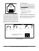
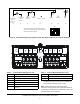
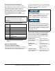
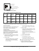
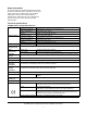
Table Of Contents

TE-6800 Series Temperature Sensors Installation Instructions
4
.
Note: Manual Override is selected for either
Terminals 1 and 6 to short sensor (with DIP switch set
for LED Off) or Terminal 6 and Terminal 8 to short LED
(with DIP switch set for LED On).
Figure 3: Terminal Block Wiring Designations (LED OFF Mode and Manual Override PB Enabled)
RTD
1
Temperature
Sensor
2
Temperature
Sensor
Common
3
Setpoint
Common
4
Setpoint
Setpoint
5
24 VAC/ +15 VDC
6
Common
7
Zone Bus
Manual
Override
Button
8
LED
LED
(3) (4) (7) (2) (5) (6) (8) (1)
Internal wiring diagram with DIP switches set as
shown on the right, LED Mode = OFF and Manual
Override push button enabled.
ON
term_bloc2
Not Connected
Modular Jack
Pin Numbers:
Figure 4: Terminal Block Location and Wiring
Table 1: Terminal Block Wiring (Part 1 of 2)
Terminal Signal Designation
1 Temperature Sensor and Manual Override
2 Temperature Sensor Common
3 Setpoint Common and LED Common
4 Setpoint
5
24 VAC (+15 VDC - VMA only)
1
6 Common (for Power, Zone Bus, or Manual
Override)
7 Zone Bus
8 LED and Manual Override
1. The +15 VDC power supply is used only when a
TE-6800 Series sensor is connected to a Variable Air
Volume Modular Assembly (VMA) controller.
Table 1: Terminal Block Wiring (Part 2 of 2)
Terminal Signal Designation