
Install Instructions

P-8000/T-5312/T-8000/T-8020 Technical Bulletin 3
1. Note the ambient
temperature or pressure at
the element.
2. Turn the dial post until the
output pressure is in the
middle of the spring range
of the controlled device, if
not already there.
3. Loosen the dial screws
without moving the dial
post. Turn the dial to
indicate the temperature or
pressure at the measuring
element, and tighten the dial
screws. (For T-5312, center
the dial. See Table 1 below
for set point dial
graduations).
4. Turn the dial to the desired
temperature or pressure set
point.
Adjusting Instructions;
Two-Position Instruments
The two-position T-8000 has
been factory adjusted to a
differential of 4F° (2C°). The
two-position P-8000 differential
has been factory adjusted for
1 PSI (7 kPa) on the low
pressure model, and 10 PSI
(70 kPa) on the high pressure
model. The two-position T-5312
is set for a differential of
0.25 PSI (2 kPa).
These two-position controllers
have been factory calibrated and
should require no additional
calibration. However, if the
factory adjustments are not the
desired differentials, or if the
instrument shows evidence of
tampering, it may be necessary
to make further adjustments.
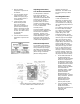
Differential Adjustment
The controller can be made to
function as a director or reverse
acting instrument by changing
the position of the differential
slider. Moving the slider upward
(Direct Acting) or downward
(Reverse Acting) from the
midpoint decreases the
differential. The slider is held
securely in place by a slotted
screw.
Checking Differential
In order to determine the
differential, the switching of the
relay must be noted. This will
occur between 3.5 and 8.5 psig
(24 and 59 kPa) pilot pressure to
the relay.
The T-8000-91 Test Gage must
be used to obtain the reading.
The T-8000-91 consists of one
1/8 in. NPT x 1/8 in. barbed
adapter fitting, 1/8 in. O.D.
polyurethane tubing, and one
0 to 30 psig (0 to 210 kPa) gage.
Insert the gage into the adapter
fitting, and connect the 1/8 in.
tubing to the 1/8 in. barb on the
adapter fitting. Remove the cap
from the proper tube on the
existing tee fitting. Connect the
tubing from the gage as shown
in Fig. 5. Pilot pressure to the
relay may now be read on the
test gage. After the instrument
has been adjusted, remove the
test gage and tubing, and recap
the proper tube of the tee fitting.
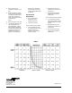
1. Set the differential slider to
the desired differential.
Table 2 shows the sensitivity
divisions in comparison to
the differential produced by
the controller. When setting
the differential for the Direct
Acting or Reverse Acting
instrument, align the bottom
of the slider with the
sensitivity division. Table 2
shows the minimum and
practical maximum
differentials which are
identical for direct or reverse
acting controllers. Practical
maximum values are
obtained with the slider
approximately 1/32 in.
(0.8 mm) from the pivot.
2. Turn the set point dial very
slowly until the pilot
pressure increases or
decreases to its minimum or
maximum value,
respectively.
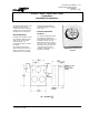
*SUPPLY AND OUTPUT CONNECTION FOR 1/4 in.
O.D. POLYTUBING UNITS TAPPED 1/8 in. NPT.
Fig. 5