
User Guide

6 T-5800-3/T-5800-4 Technical Bulletin
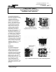
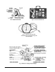
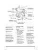
2. Rotate the master balance
screw (see Fig. 10) located
in the center of the receiver-
controller (clockwise to
increase or counterclockwise
to decrease) to produce a
9 PSIG (63 kPa) gage
reading at the master
balance “R” reference.
Doing so will shift the
working range (internally) to
a more linear portion of the
ratio circuit.
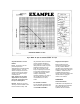
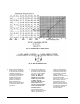
3. Vary the master input from
minimum to maximum over
its working range (Example:
0 to 60°F or 5.4 to 9 PSIG
per Fig. 6). Note: The
master “M” INPUT is
limited to not less than
2 PSIG nor greater than
17 PSIG. Note the
pressure readings at the
master balance “R”
reference corresponding
to these minimum and
maximum points.
If the minimum master
balance “R” pressure noted
above is greater than or
equal to 5 PSIG and the
maximum master balance
“R” pressure is less than
19 PSIG (with a 20 PSIG
supply), no further
adjustments are required. If
the minimum master
balance “R” pressure is less
than 5 PSIG, rotate the
master balance screw
(clockwise to increase) so
that the minimum pressure
is greater than 5 PSIG and
the maximum does not
exceed 19 PSIG.