
User Guide

T-5800-1/T-5800-2 Technical Bulletin 5
3. Start up the system to be
controlled. After a
reasonable period of time,
the receiver-controller
should be in control within
the throttling range of the
controlled device.
4. Proceed to the Gain
Adjustment section.
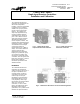
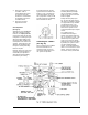
Gain Adjustment
(See Fig. 11)
Adjusting the gain dial will not
affect the controller set point;
however, the output pressure
may change when the gain dial
is adjusted. Increasing the gain
will narrow the throttling range
(decrease offset), allowing the
control point to be closer to the
set point. Decreasing the gain
will widen the throttling range,
forcing the control point away
from the set point.
Normally, having the gain arrow
set at the pointer represents a
reasonable gain adjustment
which would provide stability.
Increase the gain setting
by small increments until the
system becomes unstable and
begins to cycle. Decrease the
gain setting slightly to remove
the cycling effect. Doing so will
provide maximum controllability
with a minimum of offset.
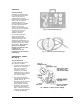
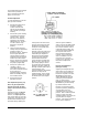
Calibrating the T-5800-2
(See Fig. 12)
When connecting the T-5800-2
Receiver-Controller to an
operating system, the fan “F”
connection should either have
the “system in operation”
function signal (minimum of
12 PSIG) attached (example:
fan on-off or water circulation
pump on-off), or the connection
must be capped.
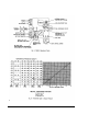
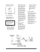
Putting the P/PI jumper (see
Fig. 13) off of its spigot causes
the receiver-controller to operate
as a proportional-only controller
(no integral function). The
jumper must be connected in
order for the system to have
normal proportional plus integral
control.
The T-5800-2 has an
automatic/manual integral
control cutout feature when the
fan “F” connection is used. This
feature keeps the system from
going out of control on startup
(after it’s been off for some time)
by allowing the system to start
up using proportional-only
control. If it is determined that
there is not a need for the cutout
feature, cap the unused fan “F”
connection. Doing so will allow