
User Guide

2 T-5800-1/T-5800-2 Technical Bulletin
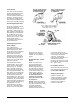
Cover Removal
The cover can be removed by
applying an inward pressure to
one of the black tabs of the
receiver-controller main body to
unlatch it. The cover can also
be removed by simply taking
hold of the top and bottom sides
of the cover and pulling outward.
Oil Indicating Supply Air Filter
Check the oil indicating supply
air filter and replace as
necessary (A-4000-137 ordered
separately). When the filter is
dirty, a pressure drop will occur.
When filtering oil-contaminated
air, the filter will change from
white to red in color. If frequent
changes are necessary, check
the air supply system to
determine the cause of dirty or
oil-contaminated air.
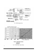
Positioning the Action and
Orifice Jumpers
The T-5800 must be
programmed according to the
system requirements. Both
single input receiver-controllers
are factory set in the direct
acting mode and can be
changed to reverse acting by
interchanging the placement of
the tube ends from one lower
spigot to the other lower spigot
(see Figs. 9 and 12).
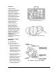
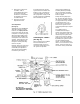
Each single input T-5800 is
furnished with a .007 in. orifice
jumper and two yellow spigot
caps (see Fig. 4). The orifice
jumper provides a restricted
source of supply to low volume
non-relay type transmitters. For
best results, it is recommended
that this jumper be used when
the low volume transmitter is
located within 50 ft. (15m) of the
receiver-controller. For all other
applications, it is recommended
that the spigots be capped and a
source of supply be furnished at
the transmitter. The non-
functional master “M” spigot
serves as a convenient storage
location for the unused orifice
jumper when the caps are
installed on the controlled
variable “CV” and supply “S”
spigots.
Set Point Selection - Local or
Remote
Local: The arrow on the
set point dial represents
approximately a 9 PSIG
(63 kPa) set point pressure.
The dial sticker is designed
so that the actual set point
can be written directly on its
surface using a common
pencil. Note: When local
set point adjustment is
used, the set point “SP”
connection must be open
to atmosphere.
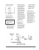
Remote: Rotate the set point
dial fully counterclockwise until
it hits its mechanical stop. Affix
the yellow dial sticker to
indicate remote set point
adjustment mode (see Fig. 5).
Connect the tubing from the
remote set point “SP” connection
of the snap-on input/output
connector. A low volume
restricted source of supply air is
automatically furnished;
therefore, use 75% of the overall
line length that is recommended
for a .005 in. orifice.
FC and PRV Test Points
The FC and PRV test points and
their associated adjustments are
for FACTORY USE ONLY.
Supply Air Interruptions
Unlike the T-5800-1, the
T-5800-2 has within its circuitry
an automatic/manual integral
control cutout feature which
requires that the supply air
remain on at all times.