
User Guide


4 Room Devices–T-4000-A.9 Product/Technical Bulletin
P
rocedures for Conversion
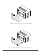
The following illustrations show various installation
situations, air connection alterations, and subplate
adaptations. Refer to page 12 for the cover plate and
Johnson Controls replacement instrument mounting
details.
Basic Steps of Installation:
1. Mount the subplate.
2. Install the pipehead and attach the tubing.
3. Install the cover plate.
4. Install the thermostat, calibrate if required.
5. Install the cover and faceplate.
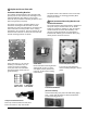
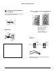
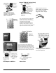
Installing Thermostat Cover Faceplate without
Window
Peel off the protective backing and the clear face
covering on the desired faceplate without window, and
install as illustrated in Figure 1.
Installing Window and Thermostat Cover
Faceplate with Window
1. Insert the window into the lower right-hand corner
opening in the front of the thermostat cover as
illustrated in Figure 2.
2. Peel off the protective backing and the clear face
covering on the faceplate with window and secure the
window into place by installing the faceplate as
illustrated in Figure 2.
Note: The window must be inserted prior to installing
the faceplate.
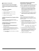
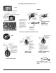
Optional External Setpoint Adjustment for
Thermostat Cover with Window
If desired, the setpoint may be adjusted without removing
the cover. The breakout feature must be removed to
access the setpoint dial. To do so proceed as follows:
Viewing the cover from the outside and using a
diagonal cutter, cut through the upper and lower
portion of the first rib located beneath the window,
remove rib and discard (refer to Figure 3). It is
recommended that a true flush blade type tool be
used to achieve a clean cut.
A thermostat adjustment tool (T-4000-119, ordered
separately) may be inserted through the breakout to
adjust the thermostat without removing the cover.
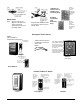
Dial Strip
A stick-on dial strip may be used to change the
thermostat setpoint dial from a horizontal to a vertical
orientation. If vertical instrument installation is desired,
proceed as follows:
1. Turn the setpoint dial clockwise until the stop pin
keeps it from turning any further.
2. Allowing for a 30F° setpoint span (a 15F° span on
either end of the desired setpoint), cut out the portion
of the dial strip that corresponds to the desired
setpoint.
Example: If the setpoint is 125°F, the span should
be 110 to 140F°. Refer to Figure 4.
3. Peel off the protective backing on the dial strip.
4. Attach the dial strip to the setpoint dial, positioning
the lowest number of the dial strip span over the
lowest number on the dial (refer to Figure 5). Turn
the dial counterclockwise while positioning the
remainder of the dial strip.
5. Calibrate the instrument if required.