
User Guide


Room Devices–T-4000-A.9 Product/Technical Bulletin 3
S
ubplate and Cover Plate with
Instrument Mounting Bracket
The subplate furnished with this kit is designed with
specific pairs of slots and holes for attaching it to the
existing installation wall, wallbox or mortar joint.
Holes are also provided for attaching the plastic cover
plate and guard kit (if required).
The plastic cover plate is furnished with the room
instrument mounting bracket attached as shown.
Generally, the new room instrument is mounted in the
same horizontal or vertical position as the existing
instrument to be converted. Thus, the bracket can be
detached and rotated 90° for alternate horizontal and
vertical mounting positions as shown.
The plastic back is also marked on the reverse side
with hole locations for mounting guard kits (when
required) as shown.
R
oom Instrument Mounting Bracket and
Terminal Connector
The room instrument mounting bracket is designed to
accept the snap-in terminal connector as shown.
Follow the orientation markings on both the bracket
and the terminal connector when installing. The
Johnson Controls pneumatic room instrument is
furnished with barbed type air terminals which plug
directly into the terminal connector.
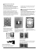
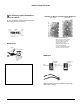
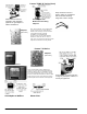
Subplate
Holes and slots 1-17 are used for
attaching to installation site, the
T-holes are used for attaching
cover plate and room instrument
mounting bracket and G-holes for
guard mounting.
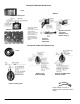
Cover Plate
Room instrument mounting bracket
attached with (2) No. 6 x 3/8 in.
self-tapping screws (detach and
rotate 90° for alternate mounting
requirements).
Cover Plate (Rear View)
Four pairs of holes marked H
and V for drilling through to mount
guard.
T-4002-3001 T-4002-3004
Wire Guard Cast Guard
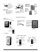
Snap-In Terminal Connector
Place top end into bracket first and press
bottom end down to snap into bracket.
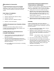
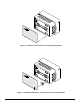
Converted Installations
(Above and Below)
Horizontal Mounting (left) and Vertical Mounting (right).
Note: Upper right and lower left views with alternate
bracket mounting positions.