
User Guide

T-3100/T-3200/T-3300 Technical Bulletin 9
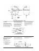
Temperature Set Point
Adjustments
T-3100 Series and T-3200 Series
1. Supply the instrument with
the proper supply air
pressure.
2. Insert the test gage
(X-200-19) and the probe
assembly (X-200-140) into
the output test port.
3. Turn the set point adjustment
screw until the pressure
reading is approximately in
the middle of the operating
range of the actuator. For
example, a 5 to 10 psig
operating range would
require an output pressure
reading of 7.5 psig.
4. Remove the test gage and
probe assembly.
5. Determine the temperature at
the measuring element.
6. Place the dial on the dial post
(do not tighten) and position
it to the temperature at the
element. Remember that
each dial increment
represents one Fahrenheit
degree. For models with
concealed adjustment, use
calibration tool X-200-136.
7. Tighten the dial and turn it to
the desired set point.
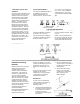
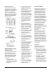
Example: Assume the desired
temperature set point is 75F and
the temperature at the element is
71F. Place the dial on the dial
post (do not tighten) and position
it to 71F or four graduations
(75F-71F±4F°) clockwise from the
middle graduation (75F), the
desired set point.
NOTE: For T-3200 Series, Low
Limit Set Point is 56F. Use
Calibration Tool X-200-136; each
graduation is 9F° (5C°).
T-3300 Series
1. Supply the instrument with
the appropriate air pressure
for the direct acting (DIR)
operation.
2. Insert the test gage and
probe assembly into the test
port.
3. Turn the DIR screw until the
output pressure is in the
middle of the actuator
operating range.
4. Change the supply air
pressure to that required for
the reverse acting (REV)
operation.
5. Turn the REV adjusting
screw until the output
pressure is in the middle of
the actuator operating range.
6. Remove the test gage and
probe assembly.
7. Determine the temperature at
the element.
8. Place the dial on the dial post
(do not tighten) and position
it to the temperature at the
element.
9. Tighten the dial and turn to
the desired set point.
NOTE: If the set points of several
instruments are to be adjusted
before switching the supply
pressure, be absolutely sure that
the temperature at the element
will not change during both
stages of adjustment.
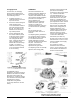
Two Element Controllers
On the T-3350 thermostat with
two elements, the averaging
element (low limit) is usually
located in the unit discharge air
and the bulb element is in the
return air chamber.
1. Insert the test gage and
probe assembly into the test
port.
2. Turn all adjusting screws
until the output pressure
reading is at maximum.
3. Turn the low limit adjusting
screw until the output
pressure is in the middle of
the actuator operating range.
4. Determine the temperature at
the low limit element.
5. Using adjusting tool
T-4002-5009 (each
graduation represents
3-1/2F° for this application),
turn the low limit adjusting
screw counterclockwise to
obtain a set point of 56F.
6. Proceed with the DIR and
REV set point adjustment(s)
as previously outlined.
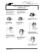
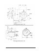
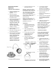
Test Gage Insertion Instructions