
User Guide

8 T-3100/T-3200/T-3300 Technical Bulletin
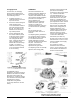
Averaging Element
In most cases, an averaging
element will be installed in the
discharge air chamber of the unit
in the following manner:
1. Install the element in a
serpentine fashion across the
top of the unit coil.
2. Secure the element along the
entire length by using
T-275-101 holders so that no
part of the element touches
the coil. The holder is very
flexible and can be bent to
any desired position.
3. On face-and-bypass units,
the element must be placed
in the space where a mixing
of coil discharge air (face)
and coil bypass air takes
place. Install the element as
close as possible to the
bottom side of the discharge
air grille. The element
should be secured by using
T-275-101 holders fastened
to the unit casing.
For ASHRAE Cycle III
applications, the element must be
installed in the mixed air (outside
and return) rather than in the
discharge air. Install the element
so it will receive the best possible
sampling of the mixture
temperature using holders
(T-275-101) fastened to the unit
casing.
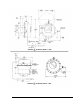
Calibration
All Johnson instruments are
carefully tested and calibrated at
the factory before shipment. If
required, field calibration should
not be started until all installation
procedures are complete. If,
during calibration, the
temperature at the measuring
element fluctuates, place the
element in a stable, well
controlled temperature area such
as a bucket of water, preferably
75F.
Be sure supply air to the
instrument is clean and free of
moisture.
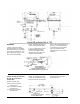
The adjusting dial is graduated in
1F° increments and is removed
with flexible hex driver X-200-18.
It is recommended that the
middle graduation be used to
represent the desired temperature
set point. Instructions for
restricting the set point
adjustment are given later.
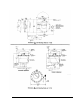
The adjusting screw for externally
adjusted, direct acting (DIR)
models is located inside the dial
post and is accessible by
removing the dial only (see detail
“A”). For DIR models with
concealed adjustment, it is
necessary to remove the small
metal button in the cover (see
detail “B”). Recalibration tool
X-200-136 should be used for set
point adjustment of these models.
It is necessary to remove the
dial and cover for models with
either reverse acting (REV) or
low limit adjustments. Use
calibration tool T-4002-5009 for
low limit adjustment on the T-
3350 (see detail “D”) and for
reverse acting adjustment of the
T-3100 and T-3300 series
thermostats (see detail “C”).
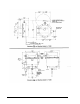
Be sure each T-3100 and T-3110
thermostat has a 0.007 in. in-line
restrictor installed in the supply
air connection.
For T-3200 and T-3250
instruments there must be a
0.007 in. in-line restrictor in the
air line between the instrument
and the room thermostat.
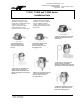
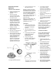
Set Point Adjustment Features
(Pictured is the Controller Portion
of the T-3350 with Two Elements)