
User Guide

T-3100/T-3200/T-3300 Technical Bulletin 7
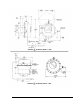
T-3350 Damper Actuator Stop
Adjustment
For correct stroke adjustment of a
damper actuator, the stop screws
should be turned in so that the
end of the piston seats against
the screws at the moment the
damper blades reach the desired
position. The piston will not
move further and no strain is
placed on the actuator shaft or
the linkage interconnecting the
actuator and damper. The force
of the air pressure acts against
the stops which are designed to
carry the force safely. It is very
important that both stop screws
be adjusted equally or the piston
will tilt within the cylinder. Be
sure the lock nuts are loosened
prior to and tightened after
adjustments are made.
Installation of Sensing
Elements
Both the bulb and the averaging
sensing elements must be
carefully located so they
measure only the intended air
temperature. The majority of
terminal air conditioning units
are very compact and little
clearance exists between coils.
Also, the air flows are of widely
varying temperature. Before
selecting an element location,
study the unit interior and make
certain that the sensing element
will not be affected by
undesirable temperatures or
mechanical damage.
Avoid extremely sharp bends in
the capillary which could
obstruct the liquid flow.
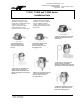
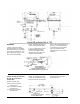
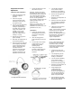
Damper Shaft Modification
A D-251-2202 Shaft Extension Kit
is available to increase the
damper shaft diameter and
extend the shaft. The kit consists
A D-251-2203 clip is available to
increase the diameter of a damper
shaft from 7/16 in. to 1/2 in.
A D-251-2204 clip is available to
increase the diameter of a damper
shaft from 3/8 in. to 7/16 in.
Route the capillary so it is not in
contact with extremely high or low
temperature sources such as
steam lines, water pipes, coils,
etc.
Be sure to route the element and
capillary so that routine
maintenance can be performed
on the terminal unit without
disturbing the element.
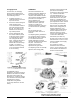
Bulb Element
In most cases, a bulb element
will be installed in the return air
chamber of the unit in the
following manner.
1. Install the element behind the
protective screen or grille and
in a location where normal
maintenance may be
performed on the unit without
interference.
of a 1-1/2 in. long coupling, 1/2
in. to 1/2 in.; a 1/2 in. diameter
shaft extension, 4-3/4 in. long;
and D-251-2203 and D-251-2204
clips.
NOTE: Both clips are required to
increase diameter of 3/8 in. shaft
to 1/2 in.
NOTE: A D-251-2203 clip can
be used to increase the size of a
10 mm shaft sufficiently to use the
D-251-2202 shaft extension kit.
2. Be sure the bulb will sense
only the return air and will not
be influenced by other air
temperatures.
3. Secure the bulb by using
holder T-275-100 which
can be hung or fastened in
place and bent to the
desired position.