
User Guide

12 T-3100/T-3200/T-3300 Technical Bulletin
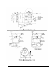
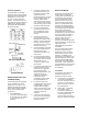
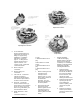
4. If the instrument has two
elements and the low limit
element must be replaced:
a. Remove the screw (1)
holding the low limit
flexure lever, spacer and
lid.
b. Remove the clip and
screw. Also remove and
save the element spacer
button.
c. Lift the element from its
socket.
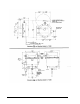
5. Remove and discard the new
element’s holding clip and
spacer button.
6. Insert the new element into
the socket and replace the
spacer button, holding clip
and screw.
7. Reassemble the flexure lever,
spring, lids and bracket.
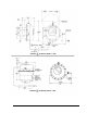
Actuators
The following instructions outline
the correct procedure for
changing the diaphragm on this
series of instruments:
1. Remove the eight (8) screws
holding the thermostat to the
integral actuator.
2. Lift the thermostat, exposing
the diaphragm. On piston
top and valve top
instruments, also remove the
piston.
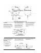
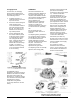
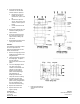
3. Turn new diaphragm inside
out, place over piston,
smooth out all wrinkles and
release any air trapped
between the head of the
piston and the diaphragm
and pull flange up.
Diaphragm will assume
shape as shown in drawing.
4. On piston top valve and
damper actuators, place the
piston exactly straight within
the new diaphragm and
insert into the bell housing.
5. Replace the thermostat.
6. Replace all screws and
tighten equally.
7. Place the instrument in
operation and check its
action.
Controls Group FAN 717.1
507 E. Michigan Street Pneumatic Control Manual
P.O. Box 423 Printed in U.S.A.
Milwaukee, WI 53202